STEP 3 - INSTALL THE U-BLOCK
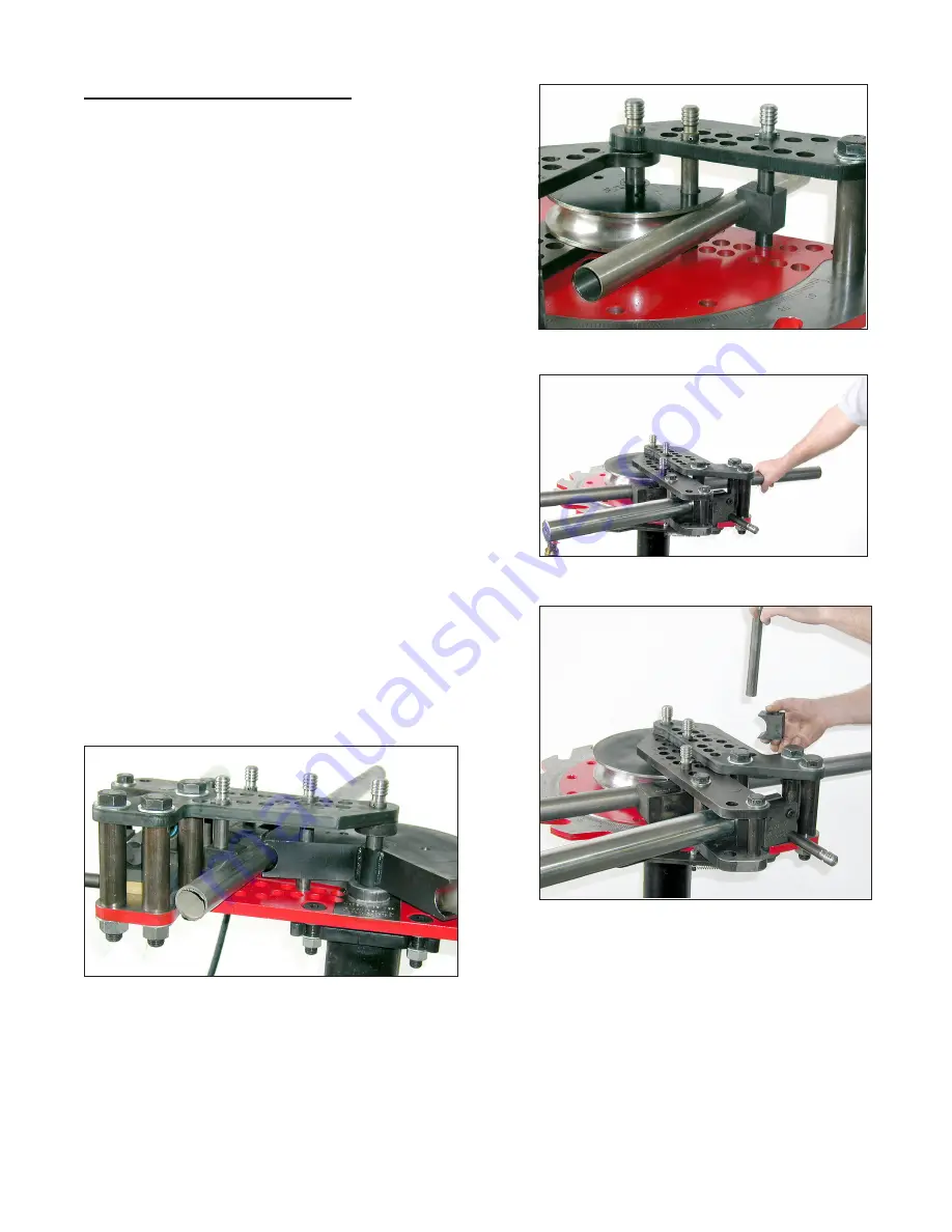
Shown in figure 23 is the U-Block installed in the bender.
Normally the pressure die would have already been installed,
but for a clearer view of the u-block it has been removed.
Looking at the top of the upper frame you will see two
rows of 7/8" holes with letters or numbers beside them. The
front seven row holes (1,2,3,4,E,F,G) are in a straight line
and the back seven holes (A,B,C,D,5,6,7) are staggered.
The back side holes are the ones where the U-Block pin is
normally installed as shown in figure 23.
PROCEDURE:
The forming die, pressure die and workpiece (tube
or pipe) have already been installed in the bender in the
previous two steps.
Position the workpiece where you want it bent. Referring
to figure 24, push the workpiece away from you firmly. This
will seat the workpiece in between the forming die and
pressure die, removing any play.
- 8 -
Install the u-block and long 7/8" frame pin into one of the
7/8" back side holes AS CLOSE TO THE 1" FRAME PIN AS
POSSIBLE. This is why you had to push the workpiece away
from you. Figure 26 shows the complete die set installed
as seen from the back side of the bender.
SQUARE TUBING
Square tube die sets are installed in the same way as round tube die sets with the exception of the
pressure die. Square tube pressure dies do not have an angled groove, just one long straight groove.
Therefore, all you need to do is install it in the correct hole# as marked on it.
Figure 23 - U-block installed
Figure 24 - Pushing workpiece
Figure 25 - Installing pin in back hole
Figure 26 - Die set installed as seen from back
side of bender


