REL 1.2
Page 36 of 82
i.MX6 Qseven PMIC SOM Hardware User Guide
iWave Systems Technologies Pvt. Ltd.
Pin
No.
Qseven Edge
Connector
Pin Name
Signal Name
i.MX6 Ball
Name/
Pin Number
Signal Type/
Termination
Description
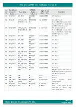
139
DP_LANE1-/
TMDS_LANE
1-
HDMI_D1M
HDMI_D1M/
J3
O, TMDS
HDMI differential data lane 1
negative.
140
DP_AUX-
NC
NA
-
NC.
141
GND
GND
NA
Power
Ground.
142
GND
GND
NA
Power
Ground.
143
D/
TMDS_LANE
0+
HDMI_D0P
HDMI_D0P/
K6
O, TMDS
HDMI differential data lane 0
positive.
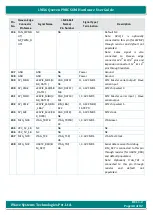
144
RSVD
NC
NA
-
NC.
145
DP_LANE2-/
TMDS_LANE
0-
HDMI_D0M
HDMI_D0M/
K5
O, TMDS
HDMI differential data lane 0
negative.
146
RSVD
NC
NA
-
NC.
147
GND
GND
NA
Power
Ground.
148
GND
GND
NA
Power
Ground.
149
D/
TMDS_LANE
2+
HDMI_D2P
HDMI_D2P/
K4
O, TMDS
HDMI differential data lane 2
positive.
150
HDMI_CTRL_
DAT
I2C2_SDA(KEY_
ROW3)
KEY_ROW3/
T7
IO, 3.3V CMOS
I2C2 data.
Note: Same signal is also
connected
to
Qseven
edge
connector 62
nd
pin.
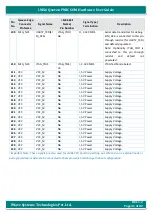
151
DP_LANE0-/
TMDS_LANE
2-
HDMI_D2M
HDMI_D2M/
K3
O, TMDS
HDMI differential data lane 2
negative.
152
HDMI_CTRL_
CLK
I2C2_SCL(KEY_C
OL3)
KEY_COL3/
U5
O, 3.3V CMOS
I2C2 clock.
Note: Same signal is also
connected
to
Qseven
edge
connector 60
th
pin.
153
DP_HDMI_H
PD#
HDMI_HPD
HDMI_HPD/
K1
I, 3.3V CMOS
HDMI Hot plug detect.
154
RSVD
TAMPER_Q7
TAMPER/
E11
I, 3V CMOS/
10K PU
Tamper Detection.
Note: This Tamper detection
input is connected to i.MX6 CPU
Tamper pin. For more details on
Tamper detection, refer i.MX6
Reference Manual.
155
PCIE_CLK_RE
F+
PCIe_REFCLK_D
P
CLK1_P/
D7
O, DIFF
PCIe differential reference clock
positive.


