REL 1.2
Page 28 of 82
i.MX6 Qseven PMIC SOM Hardware User Guide
iWave Systems Technologies Pvt. Ltd.
Pin
No.
Qseven Edge
Connector
Pin Name
Signal Name
i.MX6 Ball
Name/
Pin Number
Signal Type/
Termination
Description
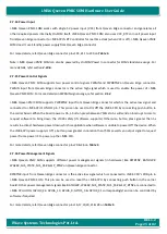
16
SUS_S5#
GPIO5_0_SUS_S
5(EIM_WAIT)
¹
EIM_WAIT/
M25
O, 3.3V CMOS/
14.7K PD
S5 state is not supported.
EIM_WAIT is connected to this
pin for GPIO purpose through
resistor and default populated.
Note: Same signal is also
optionally
connected
to
Expansion connector2 40
th
pin
through resistor and default not
populated.
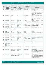
17
WAKE#
GPIO6_10_WAK
E(NANDF_RB0)
NANDF_RB0/
B16
I, 3.3V CMOS
External system wake event.
Note: NANDF_RB0 is connected to
this pin as GPIO for implementing
system wake event if required.
18
SUS_S3#
NA
NA
O, 3.3V CMOS/
10K PU
S3 state is not supported.
Note: This pin is pulled up with
10K directly.
19
SUS_STAT#
GPIO6_9_SUS_S
TAT(NANDF_WP
_B)
NANDF_WP_B/
E15
O, 3.3V CMOS
Suspend status.
Note: NANDF_WP_B is connected
to
this
pin
as
GPIO for
implementing suspend status if
required.
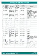
20
PWRBTN#
CPU_ON_OFF
ONOFF/
D12
I, 3V CMOS
Power button input.
Note: For more details on power
button usage, refer section
21
SLP_BTN#
GPIO3_31_SLP_
BTN(EIM_D31)
EIM_D31/
H21
I, 3.3V CMOS
Sleep button input.
Note: EIM_D31 is connected to
this pin as GPIO for implementing
sleep button functionality if
required.
22
LID_BTN#
NC
NA
-
NC.
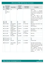
23
GND
GND
NA
Power
Ground.
24
GND
GND
NA
Power
Ground.
25
GND
GND
NA
Power
Ground.
26
PWGIN
PWRGIN
NA
I, 5V CMOS
Active high enable signal for SOM
Power.
Note: For more details on
PWRGIN, refer Section

