


- 9 -
SMX-F44
□
SMX-F441
NO
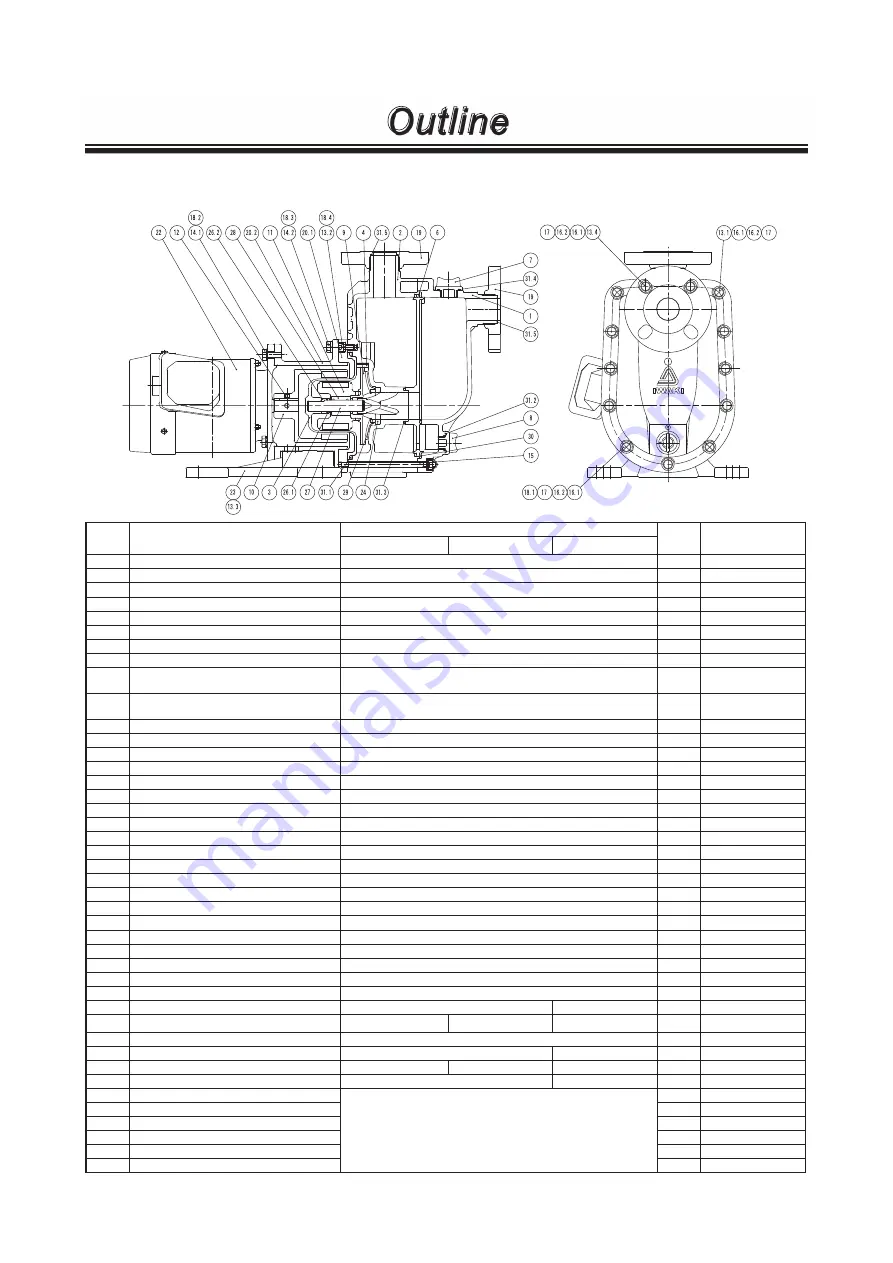
PART NAMES
MATERIAL
Q'TY
REMARKS
CF
RF
KK
1
FRONT CASE
CFRETFE
1
2
REAR CASE
CFRETFE
1
3
REAR CASING
CFRETFE
1
4
VOLUTE SPACER
CFRETFE
1
6
PLATE
CFRETFE
1
7
CAP
CFRETFE
1
8
DRAIN CAP
CFRETFE
1
9
IMPELLER
CFRETFE
1
10
DRIVE MAGNET UNIT
SMX-F441: FERRITE DUCTILE IRON
SMX-F442, 443: REAR EARTH DUCTILE IRON
1
11
MAGNET CAPSULE
SMX-F441: FERRITE CFRETFE
SMX-F442, 443: REAR EARTH CFRETFE
1
12
HEX SOCKET SET SCREW
STEEL
2
13.1 HEX SOCH HEAD BOLT
STNLS STL
6
M8×45
13.2 HEX SOCH HEAD BOLT
STNLS STL
3
M8×15
13.3 HEX SOCH HEAD BOLT
STEEL
4
M8×20 PW,SW
13.4 HEX SOCH HEAD BOLT
STNLS STL
2
M8×85
14.1 HEX HEAD BOLT
STNLS STL
4
M10×25
14.2 HEX HEAD BOLT
STNLS STL
4
M10×25
15
STUD BOLT
STNLS STL
5
16.1 NUT
STNLS STL
13
M8
16.2 COVER CAP
PE
13
17
PLAIN WASHER
STNLS STL
21
M8
18.1 SPRING WASHER
STNLS STL
13
M8
18.2 SPRING WASHER
STNLS STL
4
M10
18.3 SPRING WASHER
STNLS STL
4
M10
18.4 SPRING WASHER
STNLS STL
3
M8
19
FLANGE
CFRETFE
2
20.1 REAR CASING SUPPORT
DUCTILE IRON
1
20.2 BRACKET
DUCTILE IRON
1
22
MOTOR
-
1
23
BASE
GFRPP
1
24
LINER RING
ALUMINA CERAMICS 99.5%
SiC
1
26.1 REAR THRUST RING
-
ALUMINA CERAMICS 99.5%
-
1
ONLY RF TYPE
26.2 REAR THRUST
CFRETFE
1
27
SPINDLE
ALUMINA CERAMICS 99.5%
SiC
1
28
BEARING
High density carbon
Filled PTFE
SiC
1
29
MOUTH RING
Filled PTFE
SiC
1
30
GASKET
V:FKM E:EPDM
1
31.1 O RING (REAR CASING)
1
G-160
31.2 O RING (DRAIN CAP)
1
G-25
31.3 O RING (REAR CASE)
1
P-50
31.4 O RING (CAP)
1
G-30
31.5 O RING (FLANGE)
2
AS568-129
Outline