background image

61

5. Operation and Configuration

5.5  Multimedia functions

The Programat P710 is equipped with multimedia functions such as photo display, MP3 and video player.
The furnace is also equipped with an internal memory. Images can be saved in this memory with the help of the  
"PrograBase X10" computer software. In order to use all multimedia functions without PrograBase X10, an external  
memory (USB flash drive or SD memory card) containing the corresponding data must be connected.

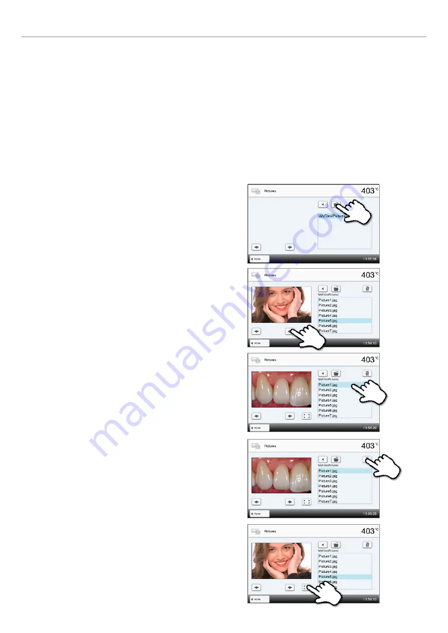
5.5.1  Image display

Scroll to page 2 in the home screen and press the  

[Images]

 button.

1. Select folder

The arrow keys are used to scroll through the folder. The folder can be 
opened by clicking the 

[Open]

 button.

2. Scroll though available image files

The arrow keys are used to scroll through the available image files. 

3. Select image

The desired image can be selected on the right side of the display. 
The left side of the display contains a preview. 

4. Delete image

The image file can be deleted by tapping the 

[Recycling bin]


button. 

5. Switch to full screen view

The corresponding button is used to switch to the full screen view. 

Summary of Contents for Programat CS3

Page 1: ...1 Programat P710 Operating Instructions Valid from software V4 0 ...

Page 2: ...2 ...

Page 3: ...oduction to the operation 23 5 2 Firing programs and programming options 26 5 3 Managing programs 41 5 4 Advanced functions of the furnace 45 5 5 Multimedia functions 61 5 6 Phone function 66 5 7 Digital Shade Assistant DSA function 68 6 Practical Use 72 6 1 Firing with an Ivoclar Vivadent program 72 6 2 Firing with an individual program 74 6 3 Important notes on the use of the infrared technology...

Page 4: ...atus Display OSD 13 Operating unit fixature 14 USB connections 15 Card reader 2 Cooling tray 4 Audio ports in out 3 Housing base 16 Cover for head opening mechanism 17 Air vents base 18 USB connection 19 USB interface 20 Ethernet connection 1 Screw for cooling tray 5 Speaker 6 Furnace feet 12b Progress display ...

Page 5: ...ng muffle 26 Furnace head sealing ring 28 Sealing surface 27 Infrared camera 38 Screw for connection cover 39 Air vents rear panel 40 Heating element fuse 41 Vacuum hose connection 42 Vacuum hose 29 On Off switch 30 Power socket 31 Power cord List of Parts 32 Rating plate 33 Vacuum pump fuse 34 Vacuum pump socket 35 Vacuum pump power cord ...

Page 6: ...ket 53 Furnace head vacuum connection 43 Furnace head mounting 44 Furnace head release 49 Heater plug 50 Heater plug socket List of Parts 60 USB download cable 61 Programat Firing Tray Kit 2 62 Programat USB stick 64 Programat WLAN stick 63 Automatic Temperature Checking Set 2 ATK 2 test set 65 Programat Bluetooth flash drive ...

Page 7: ...ructions The signs and symbols in these Operating Instructions facilitate the finding of important points and have the following meanings Symbol Note Risks and dangers Important information Contraindication Burn hazard Risk of crushing The Operating Instructions must be read 1 3 Notes regarding the Operating Instructions Furnace concerned Programat P710 Target group Dental technologists dental pro...

Page 8: ... voltage range shown on the images e g rating plate may differ depending on the voltage version of your furnace 1 5 Notes on the images in the Operating Instructions All images and illustrations in these Operating Instructions are used for exemplification and the details are not authoritative for the construction of the furnace They are symbols which may slightly differ from the original e g due t...

Page 9: ...ons to assure proper use of the furnace The instructions regulations and notes in these Operating Instructions must be observed The instructions regulations and notes in the material s Instructions for Use must be observed The furnace must be operated under the indicated environmental and operating conditions see Chapter 9 3 The Programat P710 must be properly maintained Risks and dangers The furn...

Page 10: ...re damaged There is a risk of electric shock upon contact with the heating wire Avoid damage of the insulation by contact with the investment tongs or firing tongs Contraindication Firing trays must not be placed in the area surrounding the firing table since this will obstruct the closing of the furnace head Foreign objects must not be placed on the furnace head or the air vents Make sure that no...

Page 11: ...ontains ceramic fibres and may release fibre dust Do not use compressed air or blow on the furnace thus distributing the dust in the environment and observe the additional notes on page 13 Risk of crushing burn hazard Never reach under the furnace head with the hand or other parts of the body since there is a risk of crushing and a burn hazard Never reach inside the rear cover with the hand or par...

Page 12: ...a dry soft cloth Do not use any solvents Disconnect power before cleaning and allow the furnace to cool down The furnace must be cool before it is packed for transportation Use original packaging for transportation purposes Before calibration maintenance repair or change of parts the power must be disconnected and the furnace has to be cool if it has to be opened If calibration maintenance or repa...

Page 13: ...release fibre dust Fibre dust has proved to be carcinogenic in animal experiments The heating muffle may only be dismounted by a qualified Ivoclar Vivadent After Sales Service Centre Information regarding the Safety Data Sheet is also available from your Ivoclar Vivadent After Sales Service Centre Disposal The apparatus must not be disposed of in the normal domestic waste Please correctly dispose ...

Page 14: ...ramat P710 consists of the following components Furnace base with electronic controls Furnace head with firing chamber Cooling tray Firing table Power cord and hose for vacuum pump 3 2 Hazardous areas and safety equipment Description of the hazardous areas of the furnace Hazardous area Type of risk Firing chamber Burn hazard Opening closing mechanism Risk of crushing Electrical components Risk of ...

Page 15: ...ing contact your Ivoclar Vivadent After Sales Service Centre We recommend keeping the original packaging for future service and transportation purposes 4 2 Selecting the location Place the furnace on a flat table using the rubber feet Make sure that the furnace is not placed in the immediate vicinity of heaters or other sources of heat Make sure that air may properly circulate between the wall and...

Page 16: ...ay 2 Remove the two fastening screws 1 for the cooling tray and the transport protection of the infrared camera Secure the cooling tray 2 with the two fastening screws 1 Step 2 Mounting the firing plate Place the firing plate 22 on the firing plate holder 23 If placed correctly the bottom of the firing plate is automatically centered in the firing plate holder Place the cooling tray 2 on the frame...

Page 17: ... base Proceed as follows Connect the vacuum hose 53 Insert the thermocouple plug 51 make sure that the polarity of the plug is correct Insert the heater plug 49 1 Insert the heater plug in the intended socket 2 Secure the heater plug by rotating it 45 until it snaps into place Position the furnace head mounting as shown in the picture until the furnace head audibly snaps into place Make sure that ...

Page 18: ...ction Connect the vacuum pump plug 35 with the vacuum pump socket 34 We recommend using a vacuum pump from Ivoclar Vivadent since these pumps are especially coordinated with the furnace If other pumps are used please observe and do not exceed the maximum power consumption Do not shorten the vacuum hose The minimum length of the vacuum hose is 1 6 m Step 6 Mounting the connection cover Mount the co...

Page 19: ...etely cooled down before it is removed fire hazard 4 5 Initial start up 1 Connect the power cord with the wall socket 2 Put the On Off switch 29 at the rear of the furnace on position I 4 5 1 Basic settings upon initial start up Upon the initial start up of the new furnace a number of basic settings are required These settings will be stored and will not appear anymore upon following starting proc...

Page 20: ...et the date day month year Confirm the entry with the green button By pressing the Next button you will reach the next entry screen Step 5 Enter the time Set the time hours minutes seconds Confirm the entry with the green button By pressing the Next button you will reach the next entry screen The initial start up and entry of the basic settings are now complete The furnace will now automatically c...

Page 21: ...as successful The IRT test failed Please note the error message on the display The following information is displayed Information Temperature calibration Temperature calibration of the furnace is not required Some time has passed since the last calibration Please conduct a calibration procedure Power supply The power supply voltage is in the acceptable range The power supply is outside the accepta...

Page 22: ...iring the firing chamber should be dehumidified using the dehumidification program see Chapter 5 4 for details Please note that the furnace may require a certain acclimation time after having been set up This is particularly true if the furnace was exposed to substantial temperature changes water condensation ...

Page 23: ...o a mobile phone pressing this key results in the mobile phone menu being displayed During an active phone call this key can be used to fade the mobile phone screen in or out Digital Shade Assistent key The Digital Shade Assistant DSA can be started and ended with this key 5 Operation and Configuration COOLING HEATING PREDRYING NOT READY READY Programat P710 Index Änderung Datum Name Gepr Gez Datu...

Page 24: ... home screen Close With this button you can close sub menus Confirm your entries This button is used to confirm an entry If the button appears pale green no entry has been made yet or the value entered is not in the acceptable range Cancel entry The entry can be cancelled with this button changed values are not saved Program parameter button Pressing these buttons allows you to change program para...

Page 25: ...ted To inform the user that an automatic self test has been successfully completed a preset non changeable melody is played Furnace head open and temperature below 560 C To inform the user that the temperature in the open furnace head has dropped below 560 C the selected melody is played 5 seconds In other words the furnace head is basically cool enough for the next program start The signal transm...

Page 26: ...rials b 700 free individually adjustable programs b 700 free individually adjustable programs on a USB stick The program types are subdivided into program groups Each program group consists of 20 programs All programs are equivalent and therefore full fledged programs For each program all the parameters can be adjusted a Programs for Ivoclar Vivadent materials See enclosed Program Table When the f...

Page 27: ...ams The programs and program groups can be individually named In case of software updates individually changed parameters in individual programs are NOT reset to the factory settings or changed 5 2 2 Program selection The program selection requires only few steps 1 Select program type 3 Select the program 4 Start program or edit program parameters The firing program can now be started or as an alt...

Page 28: ...ed first before any parameters can be changed The following information is displayed 1 Information line Program designation Current furnace temperature 2 Firing curve Closing time holding time Temperature increase holding temperature long term cooling Vacuum on vacuum off 3 Program options In addition to the parameters shown in the firing curve several other options are available that can be activ...

Page 29: ...e Close button to leave the Options menu Changing program options Pressing the Options button opens the menu for advanced program options Example 1 Deactivating the write protection 1 Press the Options button 2 Enter the desired holding temperature and confirm with the green button The holding temperature has been successfully changed All other parameters shown in the firing curve can be changed e...

Page 30: ... 2 Press the Pre drying temperature button 3 Enter the desired predrying temperature and confirm with the green button 4 The predrying temperature was successfully changed Press the Close button to leave the Options menu The program screen now shows the symbol pre drying active next to the Options button ...

Page 31: ...e is opened by pressing the IRT button 1 Press the IRT button 2 Select the desired IRT operating mode The menu window is automatically closed once the desired operating mode has been selected The program screen now shows the selected IRT operating mode next to the IRT button Three stage programs A three stage program permits firing procedures on three temperature levels with different parameters e...

Page 32: ...ing In addition to the three possible heating stages up to two long term cooling stages are available For one and two stage programs the configuration of the first long term cooling results in the following cooling parameters to be shown Cooling rate Long term cooling holding time 2nd long term cooling If the 2nd long term cooling has been activated switching back and forth between the parameters ...

Page 33: ... function This function can be activated by means of the Gloss Level button After the function has been activated the gloss of the restoration can be gradually increased ten gloss levels This prolongs the holding time of the corresponding firing step The temperature remains unchanged by this setting The gloss level is reset after every firing cycle or program change Proceed as follows to set the g...

Page 34: ... the vacuum is maintained during long term cooling Value range C OFF or 1 1200 C Value range F 0 or 34 2192 F Long term cooling If long term cooling is activated the furnace cools to the set temperature L at the end of the holding time with the furnace head closed Value range C OFF or 50 1200 C Value range F 0 or 122 2192 F Cooling rate Can only be set if long term cooling L is activated The cooli...

Page 35: ...perature at which the vacuum for the third temperature level is deactivated If V23 corresponds to the holding temperature the vacuum is maintained during the entire holding time Value range C Off or 1 1200 C Value range F 0 or 34 2192 F HL Holding time long term cooling The holding time for the first cooling stage indicates how long an object is fired at the long term cooling temperature Value ran...

Page 36: ... closed and when no firing process is active Programat furnaces are programmed to a stand by temperature of 403 C 757 F in the factory The temperature can be individually set for each program Value range C 100 700 C Value range F 212 1292 F Two stage programs If this function is activated the selected program can be programmed on two temperature levels Setting option On Off Three stage programs If...

Page 37: ...he vacuum pump is switched on at the end of the closing time as soon as the furnace head is closed and run until the pre vacuum time has elapsed The heating phase begins after the pre vacuum time is over The value V1 is ignored upon the start of a program with individually activated pre vacuum The vacuum remains switched on until V2 is reached V2 must be higher than the stand by temperature B Sett...

Page 38: ...t the processes are conducted as quickly and efficiently as possible The time savings compared to conventional predrying and closing processes are up to 20 IRT Plus If the operating mode IRT Plus is selected the infrared camera controls the predrying and closing processes with a reduced drying rate The closing and predrying processes are thus prolonged The operating mode IRT Plus is recommended fo...

Page 39: ...in the form of a firing curve The estimated remaining time is also displayed in 10 second intervals If no vacuum is activated the vacuum indicator and all the corresponding parameters are blank The process status is shown in colour in the firing curve Orange Program is closing the furnace head or is in predrying mode Red Program is heating up or is in holding time mode Blue Program is in long term...

Page 40: ...the Display button is pressed while the firing curve is displayed the remaining time will be shown The remaining time indicator informs the user about the time that is left until the process is completed even from a distance The remaining time is displayed in the centre of the screen in large characters The factory settings of the furnace are such that the firing curve is automatically displayed u...

Page 41: ...d the display shows a flashing Pause and the indicator changes back to the program screen If a program is stopped prematurely Vacuum release is displayed during the flooding of the firing chamber 5 2 9 Changing the parameters while the program is running Most of the parameters of the program which have not yet been executed can be changed while the program is paused Change the parameters as descri...

Page 42: ...red button is used to abort the copy process 5 3 1 Copying programs With the copy assistant individual programs program groups and program sectors can be copied The source and target of the copy process can be selected in the copy assistant Programs copied to a USB flash drive can only be opened with this furnace PrograBase X10 offers the possibility to copy the programs to other furnaces Programs...

Page 43: ... product brand for the current group can be selected 1 Press the corresponding button in the Admin menu 2 Select the desired product logo Confirm the entry with the green button 5 3 2 Resetting program to factory settings This function is used to reset a changed program to factory settings 1 Press the corresponding Execute button in the Admin menu 5 Operation and Configuration ...

Page 44: ... program and current program group can be renamed only possible for individual programs 1 Press the corresponding button in the Admin menu and select whether the program or group name should be changed 2 Enter the desired program or group name Confirm the entry with the green button ...

Page 45: ...rs in the display 4 Select the desired display brightness Confirm the entry with the green button or cancel the entry by pressing the red button The setting was changed To return to the home screen press either the touch button Home in the navigation bar or the HOME key on the membrane sealed keypad 5 4 Advanced functions of the furnace 5 4 1 Settings To reach the Settings menu scroll to page 2 in...

Page 46: ... of the acoustic signals Setting option Off 10 100 in 10 steps Melody Select the desired melody for the acoustic signal Setting option Melody 1 to 20 Time Setting the current time Setting options hh mm ss Date Setting the current date Setting options according to the set date format Date format Setting the date format Setting options dd mm yyyy mm dd yyyy Automatic power saving mode If the power s...

Page 47: ...and saved in the furnace The data can be viewed via the Diagnosis menu Setting option Inactive Printer PC Table Laboratory name The laboratory name can be entered here It is automatically added to the protocols Setting option Laboratory name entry Calibration interval Setting for the notification as to when the next calibration should be conducted Setting option 1 3 6 12 months Set heating muffle ...

Page 48: ...llogical parameters is started Setting option On Off Setting up a Bluetooth connection A Bluetooth connection with a mobile phone can be set up here See Chapter 5 4 10 for details Touch mode Setting the sensitivity of the touch screen Select Special in case of malfunctions when operating the touch screen Setting option Normal Special IRT2 After the firing process the IRT2 function measures the sur...

Page 49: ...urnace Software updates are available from www ivoclarvivadent com downloadcenter Last calibration Date of the last calibration Mains voltage Currently measured mains voltage Last dehumidification Date of the last dehumidification of the furnace Operating hours Number of operating hours Firing hours Number of firing hours Vacuum hours Number of operating hours of the vacuum pump IP address Indicat...

Page 50: ... of use Conduct the automatic temperature calibration at least every six months Temperature calibration requires only few steps 1 Open temperature calibration Scroll to page 2 in the home screen and press the Temperature calibration button The furnace must have a stand by temperature 403 C before the calibration is started 3 Remove the firing plate Remove the firing plate from the furnace and plac...

Page 51: ...nt temperature and the desired set temperature At the end of the program open the furnace head and carefully remove the ATK 2 using the furnace tongs and place it on the cooling tray to allow it to cool Replace the firing plate using the furnace tongs To return to the home screen press either the touch button Home in the navigation bar or the HOME key on the membrane sealed keypad 5 Press on sampl...

Page 52: ...ata backup With the data backup function individual programs and settings can be backed up on a USB flash drive We recommend using this feature e g before a software update or before sending in the furnace for maintenance purposes Moreover furnace data saved on a USB flash drive can be restored on the furnace However restoring only works on the same furnace with the identical serial number Data ba...

Page 53: ...rtant information Please note that modified Ivoclar Vivadent programs may be overwritten during a software update Individual programs are not affected and will not be overwritten 5 4 5 Software update Software updates can be easily installed on the furnace by means of a USB stick A USB stick which contains a current software file e g P710_V1 10 iv is required The software version on the USB stick ...

Page 54: ... firing chamber empty since an object in the chamber e g firing tray may influence the test result Conduct the heater test immediately after switching on the furnace and before any actual firing procedures are conducted If the furnace is too hot an incorrect heating muffle quality will be indicated If the heating element quality falls below 50 replacing the heating element is recommended Keypad to...

Page 55: ...agnosis function Press the Remote Diagnosis button in the Diagnosis menu 2 Generate a diagnosis file Connect a USB stick with the furnace Press the Execute button 3 Once the diagnosis file has been generated one of the following messages is displayed Diagnosis successful Diagnosis failed 4 Forward or analyze the diagnosis file Connect a USB stick with a laptop PC The file can only be analyzed by m...

Page 56: ...cation The condensation of water in the insulation of the firing chamber and the vacuum pump will result in a lower vacuum and thus in impaired firing results For that reason the furnace head should be kept closed when the furnace is switched off or the temperature is below 100 C in order to prevent the absorption of humidity Conducting the dehumidification program 1 Open the dehumidification prog...

Page 57: ...erating mode In the Settings menu various operating modes can be selected This increases the reliability of use and adjusts the furnace to the area of application The following modes are available Standard All functions of the ceramic furnace are available in this mode Protected Only programs can be selected and started in this mode Programs cannot be changed Settings or special functions cannot b...

Page 58: ... confirm the entry with the green button 4 Program screen in the Production operating mode example 2 Entering the user code Enter the user code and confirm the entry with the green button The operating modes Protected or Production can be changed by prolonged pressing of the home key at least 3 seconds ...

Page 59: ...ailable WLAN networks 3 Select the desired network 4 Enter the WLAN password and confirm with the green button or abort the entry with the red button 5 The WLAN connection was successfully set up After the initial set up of the WLAN connection the furnace automatically connects with the network last used at every new start provided the network is available Only 2 4GHz networks with the following s...

Page 60: ... is switched off The set up requires only a few steps 1 Switch on Bluetooth 2 Connect telephone with the Programat P710 A Bluetooth connection is established with the operating controls of the mobile phone Please observe the notes in the Operating Instructions of the mobile phone used 3 Enter the password for the connection if required default 0000 and confirm with the green button or abort the en...

Page 61: ...ng data must be connected 5 5 1 Image display Scroll to page 2 in the home screen and press the Images button 1 Select folder The arrow keys are used to scroll through the folder The folder can be opened by clicking the Open button 2 Scroll though available image files The arrow keys are used to scroll through the available image files 3 Select image The desired image can be selected on the right ...

Page 62: ... direction 2 Selecting music file The desired music file can be selected on the right side of the display To return to the home screen press either the touch button Home in the navigation bar or the Home key on the membrane sealed keypad 5 5 2 MP3 player Scroll to page 2 in the home screen and press the Music button 1 Select folder The arrow keys are used to scroll through the folder The folder ca...

Page 63: ...e corresponding buttons are used to change to the next or previous title as well as to start or stop or pause the playback At the end of a title the next title is automatically played 2 Selecting the video The desired video file can be selected on the right side of the display The left side of the display contains a preview 5 5 3 Video player Scroll to page 2 in the home screen and press the Video...

Page 64: ... the touch button Home in the navigation bar or the Home key on the membrane sealed keypad 3 Playback elements The corresponding buttons are used to change to the next or previous title as well as to start or stop or pause the playback At the end of a video the next one is automatically played 5 Adjusting the playback volume The corresponding button is used to adjust the volume of the play back 4 ...

Page 65: ...he Home screen and press the PDF button 1 Selecting the folder The arrow keys are used to scroll through the folder The folder can be opened by clicking the Open button 4 PDF navigation In the full screen view you can scroll through the document by swiping the screen to the left or the right Double clicking the display results in the document being shown in large format In this view you can scroll...

Page 66: ...hone key on the membrane sealed keypad to start the phone function a If the furnace is not yet connected to a mobile phone pressing this key results in the Bluetooth settings menu being displayed A connection with a mobile phone can be set up here b If the furnace is already connected with a mobile phone pressing the phone key results in the phone screen being displayed 1 A phone number can be dir...

Page 67: ... the contact list and the mobile phone supports this function the name of the caller appears at the top of the display If not the number of the caller is shown 6 If the call is accepted it can be ended by pressing the red button The end call screen can be left any time by pressing the phone key on the membrane sealed keypad in order to continue work ing at the furnace It is still possible to conti...

Page 68: ...lay contains a preview You can switch to the next or previous jpg file by pressing the Arrow Up Down buttons The marked folder can be opened by clicking the Open button The folder can be left by clicking the Back button The image displayed can be deleted by clicking the Delete button The analysis of the displayed image can be started by pressing the green button 1 Selecting the image source Store ...

Page 69: ...res the tooth to be analyzed with the reference teeth The result of the shade analysis is shown directly on the tooth to be analyzed as well as on the right side of the screen shade B1 in this example 6 Result of the manual analysis The manual analysis section is compared with the three shade guide teeth The designation of the shade guide tooth that is most similar to the section to be manually an...

Page 70: ...full screen view By double clicking the touch screen the image section can be enlarged and reduced again 7 Verifying the designations correcting If the designations of the shade guide teeth cannot be clearly recognized this screen is shown The recognized designations are shown in the three buttons below the image If necessary this designation can be corrected by pressing the corresponding button F...

Page 71: ... shown as the result If the reference teeth are incorrectly determined or unfavourable pictures are taken the DSA result will also be incorrect Further development of the software not excluded 10 Log function The current shade analysis can be saved as a log file by tapping the Disk button The log file can be printed via the PrograBase X10 software or stored as a PDF file 5 Operation and Configurat...

Page 72: ...ng on Switch on the furnace with the mains switch at the rear of the furnace The furnace conducts an automatic self test Wait until the furnace has reached the set stand by temperature and or the Optical Status Display OSD lights up green Step 2 Select the program After the self test the display shows the home screen Press the Ivoclar Vivadent programs button Select the desired program group Selec...

Page 73: ...am on the firing curve display The IRT key see Chapter 5 1 2 is used to switch to the view of the infrared camera during the closing and predrying process The corresponding key is pressed again to return to the firing curve display Once the object has reached the ideal removal temperature the display shows a corresponding notification and the cooling time elapsed As soon as the OSD lights up in gr...

Page 74: ... self test Wait until the furnace has reached the set stand by temperature Step 2 Select the program After the self test the display shows the home screen Press the Individual programs button Step 3 Entering the parameters Enter the individual parameters and create the desired firing program See Chapter 5 2 3 for details Select the desired program group Select the desired program ...

Page 75: ...hnology active position the objects in such a way that the infrared camera has a wide view of the objects Use the markings on the frame plate see Figure for orientation purposes The IRT key see Chapter 5 1 2 is used to switch to the view of the infrared camera during the closing and predrying process The corresponding key is pressed again to return to the firing curve display The furnace head open...

Page 76: ...ered metal frameworks with retentions or a holding pin have to be placed in such a way that the retentions or holding pin are not caught by the camera as this may affect the correct temperature measurement Unused firing pins or fan pins should be removed or placed outside the viewing range of the infrared camera When firing very flat objects e g veneers directly on the honey comb firing tray or fi...

Page 77: ...urnace head and furnace base are clean and undamaged Sealing rims of the furnace head and the furnace base weekly Check the membrane sealed keypad for visible damage If the membrane sealed keypad is damaged it has to be replaced by a certified Ivoclar After Sales Service Centre Membrane sealed keypad weekly Conduct temperature check Use the temperature checking set to check and adjust the temperat...

Page 78: ...ter Sales Service if necessary 7 4 Stand by We recommend keeping the furnace head closed especially if the temperature drops below 150 C If the furnace head is open there is a risk that the insulation absorbs humidity and condensation water develops during firing This negatively affects the vacuum performance and consequently the firing results 7 5 Power saving mode If the furnace is not used for ...

Page 79: ...a higher value for L1 13 yes Current temperature after start Tx 80 C Caution Excess temperature Program aborted furnace head opens to cool down the furnace 14 yes Temperature in the firing chamber 410 C at the start of the calibration program i e too high Temperature too high for calibration Furnace is cooling down Try restarting the program later 15 yes T3 T2 Enter a lower value for T2 or a highe...

Page 80: ...sured Check the following points Is the firing chamber tight no contamination on the sealing surfaces Is the vacuum hose connected Is the vacuum pump connected Is the fuse F1 in order 803 The vacuum system is not tight The tightness of the vacuum system is not given Check the sealing surfaces for possible contamination 1302 ATK2 calibration preheat 962 C Error during calibration Sample might be in...

Page 81: ... If the error persists please contact your Service Center 2757 yes Error self test An error occurred while checking the infrared camera Please switch the furnace off and on again If the error persists please contact your Service Center 2758 yes Error self test An error occurred while checking the infrared camera Please switch the furnace off and on again If the error persists please contact your S...

Page 82: ...owing error numbers is being displayed 25 29 43 44 45 46 47 48 56 103 107 108 143 144 145 146 147 148 700 701 703 704 707 1010 1011 1012 1013 1014 1015 1016 1017 1018 1019 1024 1025 1026 1028 1143 1144 1145 1146 1147 1148 1207 1300 1301 1303 1304 1305 1401 1402 1500 1750 1751 1752 1753 2001 2002 2750 2751 2752 2753 2763 2770 ...

Page 83: ...urnace to the pump and from the furnace head to the furnace base Is the pump output OK Start the vacuum test program Humidity condensation in the vacuum hose Start dehumidification program Incorrect of illogical temperature indication Is the thermocouple bent or fractured Contact your local Ivoclar Vivadent After Sales Service Centre Is the thermocouple correctly connected Correctly connect thermo...

Page 84: ...on the factory settings can be loaded In this process all programs melodies and volume adjustments are irrevocably reset to the factory settings For this purpose proceed as follows 1 Open Settings Scroll to page 2 in the home screen and press the Settings button 4 Entering the user code Enter the user code 1234 and confirm the entry with the green button or cancel the entry with the red button 2 O...

Page 85: ...settings The following messages are displayed Reset to factory settings successful Reset to factory settings failed To return to the home screen press either the touch button Home in the navigation bar or the HOME key on the membrane sealed keypad ...

Page 86: ...uations 10 Max power consumption 14 A at 100 V 12 A at 110 120 V 8 5 A at 200 240 V Acceptable data for pumps of other manufacturers Max output Final vacuum 250 W max leakage current 0 75 mA 50 mbar Only tested pumps should be used Electrical fuses 110 120 V 125 V T15 A heating circuit 125 V T 5 A vacuum pump 200 240 V 250 V T8 A heating circuit 250 V T 3 15 A vacuum pump Dimensions of electrical ...

Page 87: ...mbient temperature range 5 C to 40 C Acceptable humidity range 80 maximum relative humidity for temperatures up to 31 C gradually decreasing to 50 relative humidity at 40 C condensation excluded Acceptable ambient pressure The furnace is tested for use at altitudes of up to 2000 m above sea level 9 4 Acceptable transportation and storage conditions Acceptable temperature range 20 C to 65 C Accepta...

Page 88: ...ervice Centre Important information The current program table is also available at www ivoclarvivadent com downloadcenter The program tables can be downloaded from the Internet as PDF files Please make sure that your program table complies with the software version you use as the table is coordinated with the respective software version 10 Appendix ...

Page 89: ...89 ...

Page 90: ...90 ...

Page 91: ...91 ...

Page 92: ...izon Broadway BSD Block M5 No 1 Kecamatan Cisauk Kelurahan Sampora 15345 Tangerang Selatan Banten Indonesia Tel 62 21 3003 2932 Fax 62 21 3003 2934 www ivoclarvivadent com Ivoclar Vivadent s r l Via del Lavoro 47 40033 Casalecchio di Reno BO Italy Tel 39 051 6113555 Fax 39 051 6113565 www ivoclarvivadent it Ivoclar Vivadent K K 1 28 24 4F Hongo Bunkyo ku Tokyo 113 0033 Japan Tel 81 3 6903 3535 Fax...

Reviews: