12
6X-1050a
3960 CAMERA
INSTALLATION AND OPERATION
232
422
75 Ohm
Coax
Twisted
Data Pairs
Direct Plug-in
to Laptop
Serial Port
115 V ac
24 V ac
Connect
Either
115 V ac
or
24 V ac
(Depends on
Camera Model)
Converter
Picture
Monitor
Win
MPC
3960
Terminated 75 Ohms
Use Test Cable CTC-30 for 115 V ac use
Use Test Cable CTC-35 for 24 V ac use
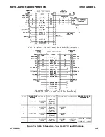
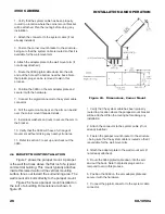
Figure 11. Interconnection Diagram, Typical Test Setup
All mounting hardware should be of high
quality stainless steel — preferably of grade 316.
This will ensure high strength fasteners resistent to
corrosion.
All mounting hole patterns discussed in this
section are four holes 90 degrees apart at the
diameters noted unless otherwise mentioned.
Mechanically indexing to a home position
should not be required since the 3960 will return to
the last position at shut down when turned on again.
Refer to section 4 at the back of this manual
for additional details concerning these various
methods of mounting a 3960 to a pole, building, or
other type of structure.
The following paragraphs describe some of the
features of the 3960 related to the installation
process.
2.8 Installation Procedure
It is important to carefully plan for all cable
routing before starting an installation. In some
situations cable will have to be pulled through
conduit or other narrow places before adding a
connector to the end of a system cable. Any
through-wall holes may require weatherproofing.
Installing the 3960 is straightforward. It is only
necessary to mount the 3960 to a suitable base,
mate the cable connector to the system cable and
apply power. This assumes the other end of the
cable is properly connected to a source of power, a
tv monitor, a graphical user interface (GUI), and any
other required equipment. Figure 11 shows a basic
setup of the 3960 in a test setup as would be used
in a test facility. This diagram should give some idea
of a typical installation. Each installation site,
though, will have its own unique requirements.
2.8.1 Camera Module Rear Panel Features
Only two features appear on the rear panel
(figure 14) of the camera module of a 3960. One is
a Schrader valve for applying dry nitrogen to the
interior of the Camera assembly housing and the
other is a 20 psig (138 kPa) pressure relief valve.
2.8.1.1 Schrader Valve
A Schrader valve is functionally identical to
those used for car tires. But this valve should be
used only to introduce dry nitrogen to a camera.
During assembly cameras are purged of normal

