11
6X-1050a
3960 CAMERA
INSTALLATION AND OPERATION
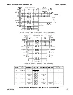
Figure 13 is a version of the cable to use with
a 3960 operating from 24 V ac.
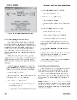
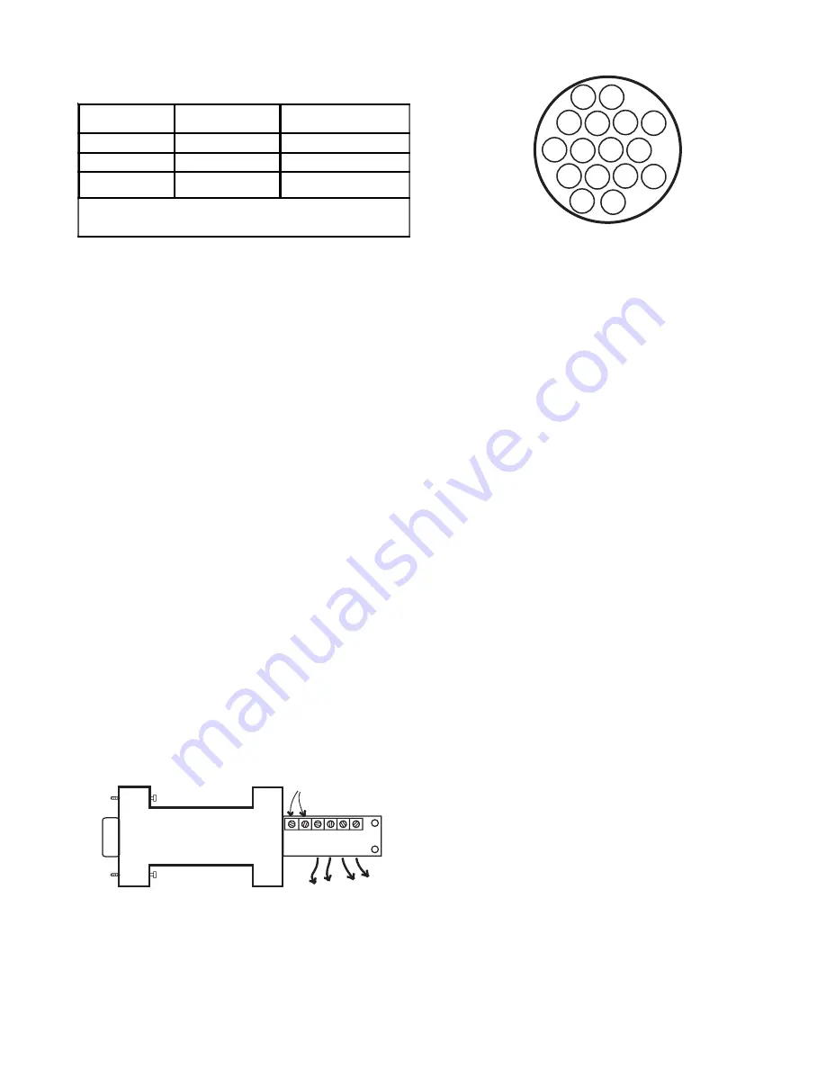
Figure 9 shows a typical 232/422 converter.
The terminal labels used on various models of
these converters differ, so it is important to read the
literature accompanying the converter being used.
Handshake is not used in this application. It is
recommended that a B & B model 422PP9TB
converter be used. This converter is available from
Cohu Electronics as part number 3010100-001.
Note that when a Local Control Panel is being
used this test/setup cable and 232/422 converter
are not required. The Panel has an RS-232 D9
connector on its front panel. The system cable from
the central control station connects to the rear of
this panel. Communications passes through the
panel to another rear panel connector to which the
3960 pigtail connector connects.
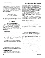
Table 6 is a list of pin functions for the connec-
tor used with a 3960 that operates from 115 V ac.
Table 7 is for the 24 V ac version of a 3960 cable.
2.6 Power Requirements
Two versions of the 3960 are available: The
model 3964 operates from 24 V ac; the 3965
operates from 115 V ac.
The maximum power requirements is 70 watts
which occurs with heaters on during cold conditions.
The line (hot) lead of 115 V ac power uses pin
12 of the connector. Neutral connects through pin
13. Ac ground is pin 15.
On a 24 V ac version of the 3960, power is
applied to pins 13 and 16.
2.7 Mounting Requirements
The dimensions shown in figure 8 related to
mounting the 3960. The 3960 can be optioned for
six different mounting configurations:
1. Direct mounting to the base plate on the 3960.
See section 4.1 for details about this standard mount-
ing base.
2. Mounting to a second, larger circular mounting
base which then mounts to a suitable surface. See
section 4.2 for mounting with this option.
3. Wall Mount Arm (for direct mounting to a suitable
wall surface or for mounting to items 4, 5, or 6 below)
4. Pole Mount. Clamps to a pole using stainless steel
straps. The wall mount arm then attaches to this pole
mount.
5. Corner Mount. Bolts to the corner of a building or
other structure. The wall mount arm then attaches to
this corner mount.
6. Parapet Mount. Bolts to the inside of a parapet on
a roof of a building or other structure. The wall mount
arm then attaches to the parapet.
Figure 10. Pin Location Diagram,
3960 Pigtail Connector
Figure 9. Typical 232/422 Converter
Table 5. 3960 Connector & Mating Cable Plug
DESCRIPTION CAMERA PIGTAIL
CONNECTOR
MATING SYSTEM
CABLE PLUG
C onnector Housing
1310306-010
C ohu 1310307-009
Backshell
1310307-103
Cohu 1310307-103
Contacts (11 each)
Pins
1310308-001
Sockets
C ohu 1310308-002
One end of cam era 34-inch pigtail cable is perm anently attached to
base of cam era and the other end is term inated with the pigtail
connector.
16
15
11 12 13 14
1
2
3
4
5
6
7
8
9 10
Mating View of Connector on Cable
Attached to Camera Base
232
D9
FEMALE
B & B
Model 422PP9TB
B&B Electronics
707 Dayton Road
PO Box 1040
Ottawa IL 61350
www.bb-elec.com
+12V
GND
RD(B)
RD(A)
TD(A)
TD(B)
422
CONVERTER
(Available from Cohu as Part Number 3010100-001)
Rx-
Rx+
Tx+ Tx-
TO 3960
POWER
MAY BE REQUIRED
WITH CA-297C CABLE

