MARCH 2004
DISCHARGE
9.95
MARINE ENGINES INSTALLATION
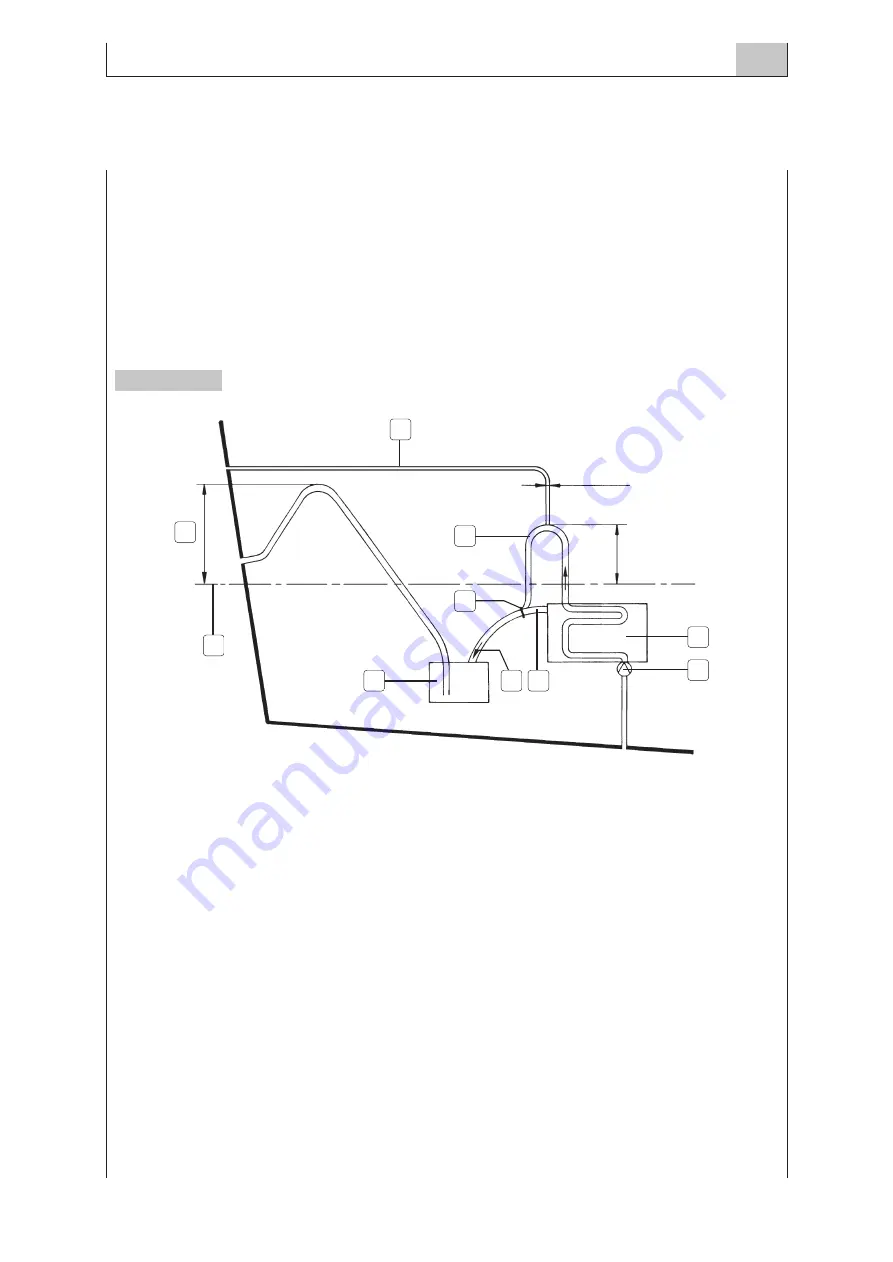
The overboard discharge pipe is also an inverted U-shaped tube that hinders direct outside water flow-
ing; its height depends on the kind of vessel.
The silencer capacity must be superior to the water volume discharged when stopping the engine.
Materials used must be resistant to exhaust gases and seawater aggression. It is advisable to use stain-
less steel and to avoid using copper and bronze.
The dockyard shall be responsible for preventing corrosion phenomena, mainly when the discharge
pipe is below the water line.The staff must also check that the system works correctly.
Besides, the dockyard personnel should pay special attention to avoid uncovered sections on those spe-
cial raisers and insulated pipes and to ensure that they are water-cooled to avoid heat radiation that
may cause burning or fire danger.
1.Vent pipe - 2. Waterline - 3. Secondary cooling circuit discharge - 4. Engine - 5. Secondary cooling
circuit pump - 6. Silencer - 7. Gas and seawater flow- 8. Engine discharge - 9. Mixing area -
A. Elevation depending on the type of installation.
It is important to choose the right gases exhaust position to avoid their flowing into vessel passenger
or crew areas.
In the case of large superstructures, usually there is an aft turbulence zone that favours residual gases.
Therefore, the layout of pipe ends must be carefully planned to avoid such zone.
The dockyard personnel must make sure that the pipes are correctly fastened to the hull and that use-
less water accumulation is not formed.
NOTE
Dry discharge systems, as well as mixers, are subjected to corrosion and wear and tear caused by the con-
stitutive material and the circulating fluids.
They must be periodically controlled and the worn out parts must be changed, if necessary, to guarantee com-
fort and safety.
Figure 2
A
1
Ø from 5 to 6 mm
300 mm MIN
2
4
5
6
9
8
7
3
Summary of Contents for Marine Diesel Engines
Page 1: ...MARINE DIESEL ENGINES INSTALLATION HANDBOOK T E C H N O L O G I C A L E X C E L L E N C E ...
Page 8: ...MARCH 2004 INTRODUCTION 1 8 MARINE ENGINES INSTALLATION ...
Page 24: ...MARCH 2004 ENGINE BOAT CHOICE FACTORS 2 24 MARINE ENGINES INSTALLATION ...
Page 34: ...MARCH 2004 DRIVE 3 34 MARINE ENGINES INSTALLATION ...
Page 50: ...MARCH 2004 DRIVE 3 50 MARINE ENGINES INSTALLATION ...
Page 52: ...MARCH 2004 ENGINE INSTALLATION 4 52 MARINE ENGINES INSTALLATION ...
Page 60: ...MARCH 2004 AIR SUPPLY 5 60 MARINE ENGINES INSTALLATION ...
Page 64: ...MARCH 2004 AIR SUPPLY 5 64 MARINE ENGINES INSTALLATION ...
Page 66: ...MARCH 2004 FUEL SUPPLY 6 66 MARINE ENGINES INSTALLATION ...
Page 74: ...MARCH 2004 FUEL SUPPLY 6 74 MARINE ENGINES INSTALLATION ...
Page 76: ...MARCH 2004 LUBRICATION 7 76 MARINE ENGINES INSTALLATION ...
Page 80: ...MARCH 2004 LUBRICATION 7 80 MARINE ENGINES INSTALLATION ...
Page 82: ...MARCH 2004 COOLING 8 82 MARINE ENGINES INSTALLATION ...
Page 92: ...MARCH 2004 DISCHARGE 9 92 MARINE ENGINES INSTALLATION ...
Page 98: ...MARCH 2004 DISCHARGE 9 98 MARINE ENGINES INSTALLATION ...
Page 100: ...MARCH 2004 AUXILIARY SERVICES 10 100 MARINE ENGINES INSTALLATION ...
Page 104: ...MARCH 2004 AUXILIARY SERVICES 10 104 MARINE ENGINES INSTALLATION ...
Page 106: ...MARCH 2004 CONTROLS 11 106 MARINE ENGINES INSTALLATION ...
Page 110: ...MARCH 2004 ELECTRICAL INSTALLATION 12 110 MARINE ENGINES INSTALLATION ...
Page 120: ...MARCH 2004 GALVANIC CORROSION PROTECTION 13 120 MARINE ENGINES INSTALLATION ...
Page 126: ...MARCH 2004 CONTROL TEST PROCEDURES 14 126 MARINE ENGINES INSTALLATION ...
Page 131: ......


