■
It shall be made with materials able to resist chemical agents and hot fuel for the whole boat life.
Metal reservoirs protected through zinc-coating or copper-coating galvanic treatments are not suit-
able to contain “diesel fuel” as the sulphur in the fuel can generate chemical reactions, thus pro-
ducing sulphate dangerous for the injection system. If welded reservoirs are used, make sure they
do not release welding dust or sludge.
■
It shall be fitted with a breather to prevent pressurisation and depression. Foresee also a breather
valve to stop the fuel leak in the event of capsizing, preventing at the same time dust and water
from getting inside.
■
It shall ensure a fuel reserve in any condition. For this purpose, the instrument panel shall be fitted
with a fuel level gauge or an alarm for the fuel low level. Verify that the engine delivers the maxi-
mum power even when only the reserve quantity is present.
For any solution, it is requested to respect the depression limit values of the suction pipe when the fil-
ter is clogged and the counter-pressure values of the fuel return pipe to the reservoir.
Further specifications are given in the installation diagrams relevant to each engine.
NOTE
On the boats fitted with many reservoirs, to prevent excessive suction depression it is suggested to use a
small reservoir, called service reservoir, placed next to the engines and to which the main reservoirs will be
connected to ensure the required autonomy.
With service reservoirs, you are suggested to connect the fuel return pipe from the engine to the main reser-
voir to prevent the service reservoir overheating and derating. It is also advisable to check that the transfer
from the main reservoir to the service reservoir is ensured at each fuel level and for each sailing trim.
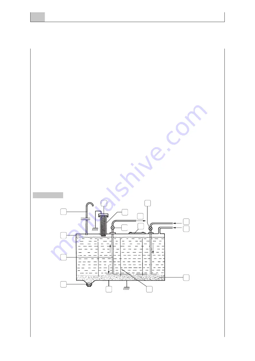
Figure 5 illustrates what mentioned above.
1. Waterproof filling plug - 2. Mesh filter - 3.To the decanting prefilter - 4. Cleaning mobile panel -
5. 5% volume of sedimentation tank - 6. Water breaker baffles - 7. Distance from the
bottom from 20 to 30 mm - 8. Draining plug - 9. Fuel pipe - 10. 1.5% volume for fuel expansion -
11. Swan neck breather - 12. Cock - 13. Fuel return - 14. Injector draining (when used).
MARCH 2004
FUEL SUPPLY
6.70
MARINE ENGINES INSTALLATION
Figure 5
1
2
3
12
13
14
5
7
6
8
10
11
9
4
12
Summary of Contents for Marine Diesel Engines
Page 1: ...MARINE DIESEL ENGINES INSTALLATION HANDBOOK T E C H N O L O G I C A L E X C E L L E N C E ...
Page 8: ...MARCH 2004 INTRODUCTION 1 8 MARINE ENGINES INSTALLATION ...
Page 24: ...MARCH 2004 ENGINE BOAT CHOICE FACTORS 2 24 MARINE ENGINES INSTALLATION ...
Page 34: ...MARCH 2004 DRIVE 3 34 MARINE ENGINES INSTALLATION ...
Page 50: ...MARCH 2004 DRIVE 3 50 MARINE ENGINES INSTALLATION ...
Page 52: ...MARCH 2004 ENGINE INSTALLATION 4 52 MARINE ENGINES INSTALLATION ...
Page 60: ...MARCH 2004 AIR SUPPLY 5 60 MARINE ENGINES INSTALLATION ...
Page 64: ...MARCH 2004 AIR SUPPLY 5 64 MARINE ENGINES INSTALLATION ...
Page 66: ...MARCH 2004 FUEL SUPPLY 6 66 MARINE ENGINES INSTALLATION ...
Page 74: ...MARCH 2004 FUEL SUPPLY 6 74 MARINE ENGINES INSTALLATION ...
Page 76: ...MARCH 2004 LUBRICATION 7 76 MARINE ENGINES INSTALLATION ...
Page 80: ...MARCH 2004 LUBRICATION 7 80 MARINE ENGINES INSTALLATION ...
Page 82: ...MARCH 2004 COOLING 8 82 MARINE ENGINES INSTALLATION ...
Page 92: ...MARCH 2004 DISCHARGE 9 92 MARINE ENGINES INSTALLATION ...
Page 98: ...MARCH 2004 DISCHARGE 9 98 MARINE ENGINES INSTALLATION ...
Page 100: ...MARCH 2004 AUXILIARY SERVICES 10 100 MARINE ENGINES INSTALLATION ...
Page 104: ...MARCH 2004 AUXILIARY SERVICES 10 104 MARINE ENGINES INSTALLATION ...
Page 106: ...MARCH 2004 CONTROLS 11 106 MARINE ENGINES INSTALLATION ...
Page 110: ...MARCH 2004 ELECTRICAL INSTALLATION 12 110 MARINE ENGINES INSTALLATION ...
Page 120: ...MARCH 2004 GALVANIC CORROSION PROTECTION 13 120 MARINE ENGINES INSTALLATION ...
Page 126: ...MARCH 2004 CONTROL TEST PROCEDURES 14 126 MARINE ENGINES INSTALLATION ...
Page 131: ......


