AF (6-36) IOM
19
screw holders un-grouted.
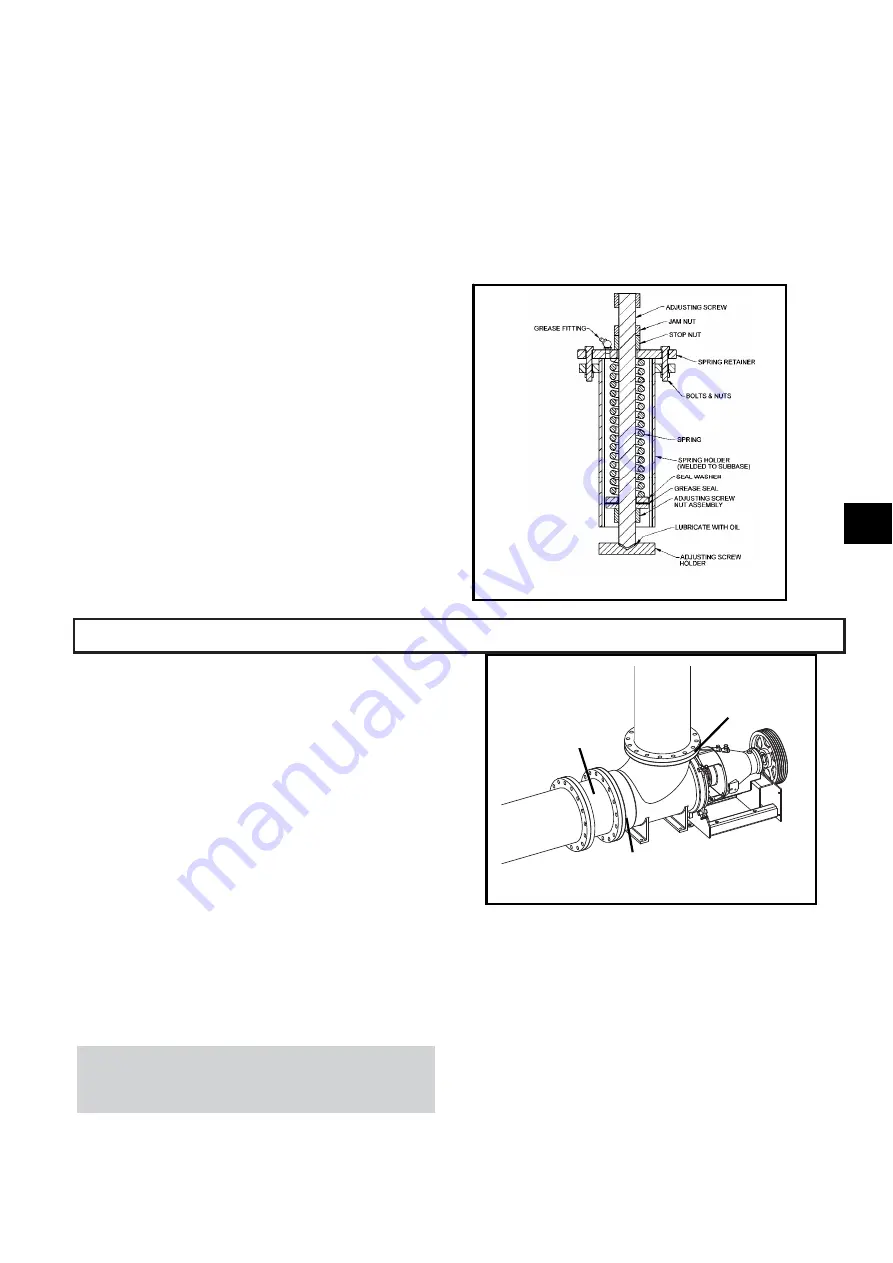
If it becomes necessary to remove a spring assembly
from a spring pocket, for safety the following steps
should be strictly adhered to:
1. Make sure the spring is relaxed. If the spring cannot
be relaxed with the adjusting screw, the safest
method is to cut the coils using a torch.
2. Remove the bolts or cap screws, which fasten the
spring retainer to the holder and lift out the entire
assembly.
3. When the pump is connected to the system and a
spring is removed, there should be support under
the sub-base near the spring location until the spring
has been replaced and adjusted. Distortion of the
sub-base will affect the pump alignment,
4. and the weight of the components is more likely to
cause distortion when the pump is connected to the
rigid pipe system.
5. If a spring is replaced while the system is hot, the
stop nut should not be set until the system is cold.
6. The springs must be allowed to push the base back
to its cold position.
An optional grease filled spring pocket is shown in figure
13. The difference between the standard pocket and the
grease filled pocket is the addition of a grease fitting and
grease seal. Adjustment and setting of the grease filled
pocket are identical.
PIPE HUNG INSTALLATIONS
PIPE SUPPORT DESIGN REQUIREMENTS
1. Piping supports must meet Hydraulic Institute,
ASME/ANSI, DIN requirements, in conjunction
with standard construction practices.
2. Piping shall be stiff enough to prevent unwanted
pump vibrations.
3. Thermal expansion of the piping must be
accounted for by the piping/system designer.
4. Refer to the installation/dimensional drawing for
pump weights
5. Refer to pump flange load drawing for allowable
loads
6. Follow the power transmission manufacturer’s
recommendations for angular limits and thermal
movement of the pump relative to pump driver.
NOTE: Future access to the pump impeller and
shaft will require removal of a section of the
horizontal pipe. The piping shall have a spool
piece for this purpose (See Fig. 14).
INSTALLATION OF THE PUMP IN THE
PIPING
1. Connect the elbow upper flange to the vertical
pipe run and tighten the flange bolts.
2. Check the impeller clearance in the elbow/casing
to be sure it is well centered using the criteria that
the minimum gap at the vane O.D. is at least ½
the maximum gap. See the impeller check sheet
on pg. 28 of this IOM.
Fig. 14
Spool
Piece
Lower
Flange
Upper
Flange
Fig. 13
3
Summary of Contents for Goulds Pumps AF
Page 1: ...Installation Operation and Maintenance Instructions Model AF 6 36 MXR Bearings ...
Page 3: ...AF 6 36 IOM 6 THIS PAGE INTENTIONALLY LEFT BLANK ...
Page 5: ...AF 6 36 IOM 8 THIS PAGE INTENTIONALLY LEFT BLANK ...
Page 14: ...10 AF 6 36 IOM THIS PAGE INTENTIONALLY LEFT BLANK ...
Page 32: ...28 AF 6 36 IOM ...
Page 34: ...30 AF 6 36 IOM THIS PAGE INTENTIONALLY LEFT BLANK ...
Page 48: ...44 AF 6 36 IOM THIS PAGE INTENTIONALLY LEFT BLANK ...
Page 66: ...62 AF 6 36 IOM AF SECTIONAL shown with optional restrictor bushing adapter Fig 77 ...
Page 68: ...64 AF 6 36 IOM AF OPTIONS Fig 78 351 370F 126 ...
Page 69: ...AF 6 36 IOM 65 MXR BEARING CONFIGURATIONS 1MXR 3MXR 4MXR 6MXR Fig 79 540C 6 ...
Page 72: ...68 AF 6 36 IOM THIS PAGE INTENTIONALLY LEFT BLANK ...


