1
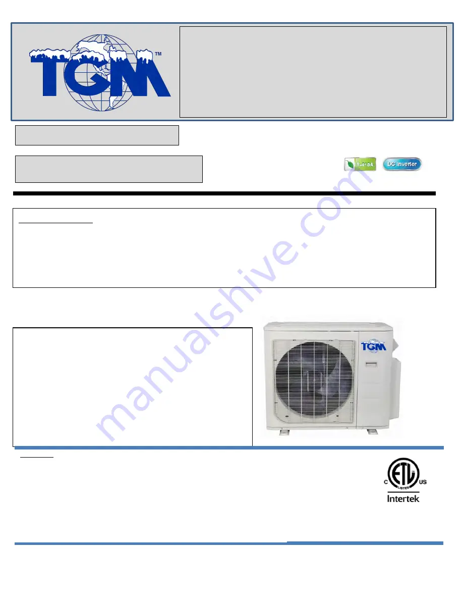
Multi outdoor units
sErViCE MAnuAl
Multi zone
CondEnsinG units
Revision E:
ODMFI-E-1705
Model Numbers:
MMCUT18AS2
MMCUT27AS3
MMCUT36AS4
MMCUT48AS5
WARNING
•
Installation MUST conform with local building codes or, in the absence of local
codes, with the National Electrical Code NFPA70/ANSI C1-1993 or current edition
and Canadian Electrical Code Part1 CSA C.22.1.
•
The information contained in the manual is intended for use by a qualified service
technician familiar with safety procedures and equipped with the proper tools and
test instruments
•
Installation or repairs made by unqualified persons can result in hazards to you
and others.
•
Failure to carefully read and follow all instructions in this manual can result in
equipment malfunction, property damage, personal injury and/or death.
Table of Contents
1.
Indoor Unit Combination
2.
Dimension Of Outdoor Unit
3.
Refrigerant Cycle Diagram
4.
Installation Details
5.
Electronic Function
6.
Wiring Diagrams
7.
Trouble Shooting
8.
Disassembly Instructions
Summary of Contents for MMCUT18AS2
Page 3: ...3 MMCUT36AS4 WD30 metal plate 114 MMCUT48AS5 WE30 metal plate 121...
Page 10: ...10...
Page 23: ...23 6 Wiring Diagrams 6 1 Wiring diagram of 1 drive 2 outdoor MMCUT18AS2...
Page 24: ...24 6 2 Wiring diagram of 1 drive 3 outdoor MMCUT27AS3...
Page 25: ...25 6 3 Wiring diagram of 1 drive 4 outdoor MMCUT36AS4...
Page 29: ...29...
Page 43: ...43 Operating Standby Pic 2 IPM for 2 zone 3 zone...
Page 59: ...59 Operating Standby Pic 2 IPM board for 2 zone 3 zone...
Page 66: ...66 IPM board for 2 zone 3 zone...
Page 68: ...68 IPM board for 4 zone...
Page 71: ...71 Two ports of the inductance Inductance...
Page 74: ...74 Vs Vcc Vsp FG...
Page 77: ...77...
Page 80: ...80...
Page 83: ...83...
Page 94: ...94 6 EXV check Disconnect the connectors...
Page 96: ...96 Red Blue Red Yellow...
Page 97: ...97 Brown Orange...
Page 98: ...98 Brown White...
Page 108: ...108 Screws of right rear panel Screws of terminal board...


