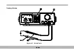
①
.
Turn
the
Selector
to Resistance
and
Continuity
Measurement
.
②
.
Connect
the
leads
as
shown
.
③
.
is
not
available
in
the
continuity
test
;
all
other
buttons can be used
.
The
Resistance
or
Continuity
measurement
is
changed
alternatively
by
each
press
the
button
.
The
Resistance
Measurement
is
as
follows
:
1
.
Select
the
Resistance Measurement
by
Pressing
the
.
2
.
Insert
the
black
and
red
test
leads
into
the
COM
and
V
Ω
Hz
input terminals respectively
.
3
.
Select
the
desired
ohms
(
Ω
)
range
or
to
set
auto
-
range
.
Connect
the
black
and
red
test
probe
tips
to
the
circuit
or
device
under test, making
sure
it
is
de
-
energized
first.
4
.
Turn
off
any
power
to
the
resistor
to
be
me asured
.
Discharge
any
capacitor
.
Any
voltage
present
during
a
resistance
measurement
will
cause inaccurate readings and
could
damage
the
meter
if
exceeding
the
overload
protection
of
250V
DC
or
AC
rms
.
5
.
Open
circuits
will
be
displayed
as
an
overload
condition
and
MSD
(
Most
Signification
Digit
)
blinks
.
7
.
The
resistance
in
the
test
leads
c an
diminish
accuracy
on
the
lowest
(
400
Ω
)
range
.
The
error
is
usually
0
.
1
to
0
.
2
Ω
for a standard
pair
of
test
leads
.
To
determine
the
error
,
short
the
test
leads
together
and
then
use
the
Relative
mode
to
automatically
subtract
the
lead resistance
from
resistance
measurements
.
2-17
Summary of Contents for M9803R
Page 1: ...Bench Multimeter Users Manual M9803R...
Page 8: ...Instrument Layout Figure 1 1 Bench Multimeter Features Forward 1 2...
Page 9: ...Figure 1 2 Bench Multimeter Features Backward 1 3...
Page 18: ...Measuring DC Volts Figure 2 1 DC Volts Measurements 2 2...
Page 20: ...Measuring AC Volts Figure 2 2 AC Volts Measurements 2 4...
Page 22: ...Measuring DC and AC Amps Figure 2 3 Amps Measurements 2 6...
Page 24: ...Measuring DC and AC Milliamps Figure 2 4 Milliamps Measurements 2 8...
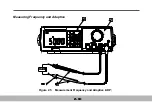
Page 26: ...Measuring Frequency and Adaptive Figure 2 5 Measurement Frequency and Adaptive ADP 2 10...
Page 28: ...Measuring Capacitance Figure 2 6 Capacitance Measurements 2 12...
Page 30: ...Testing Diodes Figure 2 7 Diode Tests 2 14...
Page 32: ...Measuring Resistance and Continuity Figure 2 8 Resistance and Continuity Measurements 2 16...


