isweek M9803R User Manual Download Page 2

Introduction


This

manual

contains

information

and

warnings

,

which

must

be

followed

to

ensure

safe

operation

and

retain

the

meter

in

safe

condition

.


WARNING


 READ

SAFETY INFORMATION”BEFORE USING THE BENCH  MULTIMETER


This

multimeter

is

a

portability

4000

-

count

instrument

that

is

designed

for

use

in

the

laboratory

,

field

servicing

,

and

at

home

,

and

any

circumstance

.

This

multimeter

feature

compact

design

with

rounded

corners

for

easy

handling

and

has

a

rugged

case

in

shock

resistant

and

fire

-

retardant

.

And

electronic

overload

protection

for

all

functions

and

ranges

.


Unpacking

and

Inspection


Upon

removing

your

new

Bench

Multimeter

from

its

packing

,

you

should

have

the

following

items

:

1

.

Bench

Multimeter

2

Test

Leads

set

(

one

black

,

one

red

)

3

.

Carrying

strap

4

.

Power

Cord


5

.

Instruction

Manual

6

.

RS232C

Cable

(

to

buy

by

user

optional

)

If

any

of

the

above

items

are

missing

or

are

received

in

a

damaged

condition

,

please

contact

the 

distributor

from

whom you purchased the unit. 


Ⅰ 

Summary of Contents for M9803R

Page 1: ...Bench Multimeter Users Manual M9803R...

Page 2: ...compact design with rounded corners for easy handling and has a rugged case in shock resistant and fire retardant And electronic overload protection for all functions and ranges Unpacking and Inspect...

Page 3: ...ecautions Safety Information 1 A Quick Tour 1 1 Symbol Explanation 1 1 Instrument Layout 1 2 Using the Rotary Switch 1 5 Using the Hardkeys 1 6 Buzzer Output 1 10 Low Battery Indication 1 10 2 Making...

Page 4: ...Capacitance 2 10 Measuring Frequency and Adaptive 2 12 Testing Diodes 2 14 Measuring Resistance and Continuity 2 16 3 Specifications 3 1 General Specifications 3 1 Resolution and Accuracy 3 3 4 Mainte...

Page 5: ...etc do not attempt to take measurements 3 Never ground yourself when taking electrical measurements Do not touch exposed metal pipes outlets fixtures etc which might be at ground potential Keep your b...

Page 6: ...y Take a reading of a known voltage or current before assuming a zero reading indicates no current or voltage 12 Do not attempt calibration or service unless trained and another person capable of rend...

Page 7: ...r Symbol Explanation Earth ground TERMINAL AC Alternating current DC Direct current Audible continuity Equipment protected throughout by Double Insulation Protection Class 1 1 Caution Caution Possibil...

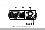
Page 8: ...Instrument Layout Figure 1 1 Bench Multimeter Features Forward 1 2...

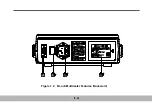
Page 9: ...Figure 1 2 Bench Multimeter Features Backward 1 3...

Page 10: ...Milliamp Input Terminal This is the positive input terminal for current measurement AC or DC up to 400 mA Connection is made to using the Red test lead 4 A 10 Amperes Input Terminal This is the positi...

Page 11: ...oltge value of AC power must be examined with same the power requirements of multimeter before connect power cord to live power source and the switch is turned on This switch is used to turn AC Power...

Page 12: ...d alternatively by each press button In the range of Measuring Frequency and Adapted Test The Frequency or Adaptive measurement is changed alternatively by each press button In the range of Measuring...

Page 13: ...s come out when occur the over range or continuity modes And the range is also changed if it is in auto range 4 Delay Data Hold DELAY HOLD Button When button is pressed over eight second to toggle in...

Page 14: ...ld to just before range 6 Relative Display REL Button Press button to enter the Relative Display mode the REL annunciator turns on zero the display and store the displayed reading as a reference value...

Page 15: ...ng And the Data Recall Hold mode is released by pressing button or button Press button to select the Manual Range mode and turn off the AUTO annunciator 7 RANGE Button In the Manual Range mode each ti...

Page 16: ...ta for you necessary Buzzer Output 2kHz buzzer sound is output in following cases 1 When operate the key 2 When occur the over range Except the measurement mode of Resistance Frequency Hz Continuity a...

Page 17: ...power cord to live power source and the switch is turned on Before making any measurements always examine the multimeter and accessories used with the multimeter for damage contamination excessive di...

Page 18: ...Measuring DC Volts Figure 2 1 DC Volts Measurements 2 2...

Page 19: ...known always start with the highest range 4 Connect the test lead tips in parallel with the circuit to be measured Be careful not to touch any energised conductors Note the reading 5 For DC voltage re...

Page 20: ...Measuring AC Volts Figure 2 2 AC Volts Measurements 2 4...

Page 21: ...2 Select the desired AC voltage range or set automatic range 3 When the magnitude of the voltage to be measured is unknown always start with the highest range 4 Connect the test lead tips in parallel...

Page 22: ...Measuring DC and AC Amps Figure 2 3 Amps Measurements 2 6...

Page 23: ...y by each press the button The DC and AC Amps Measurement is as follows 1 Insert the black and red test leads into the COM and A input terminals respectively 2 Turn off or disconnect the circuit to be...

Page 24: ...Measuring DC and AC Milliamps Figure 2 4 Milliamps Measurements 2 8...

Page 25: ...asurement is as follows 1 Insert the black and red test leads into the COM and mA input terminals respectively 2 Select the desired DC current range or AC current range 3 Turn off or disconnect the ci...

Page 26: ...Measuring Frequency and Adaptive Figure 2 5 Measurement Frequency and Adaptive ADP 2 10...

Page 27: ...esolution Manual range is not available 3 Determine that the amplitude level of the signal to be measured is not greater than the input voltage limit 250V DC AC rms The signal amplitude mustalso be gr...

Page 28: ...Measuring Capacitance Figure 2 6 Capacitance Measurements 2 12...

Page 29: ...or 5 Read capacitance value directly from display The measurement accuracy of capacitors can be improved by first using the Relative mode to zero the and automatically subtract the residual multimeter...

Page 30: ...Testing Diodes Figure 2 7 Diode Tests 2 14...

Page 31: ...follows 1 Set the position by turning the rotary switch 1 Insert the black and red test leads into the COM and V Hz input terminals respectively 2 The red lead should be connected to the anode and the...

Page 32: ...Measuring Resistance and Continuity Figure 2 8 Resistance and Continuity Measurements 2 16...

Page 33: ...the circuit or device under test making sure it is de energized first 4 Turn off any power to the resistor to be me asured Discharge any capacitor Any voltage present during a resistance measurement...

Page 34: ...o the COM and V Hz input terminals respectively 3 Connect the black and red test probe tips to t he circuit or device under test making sure it is de energized first 4 An audible tone will sound for r...

Page 35: ...42 segment analog bar graph Full annunciates automatic polarity indication Measuring rate Digit 2 times per second Analog bar graph 20 times second Capacitance 1 time per second Overrange indications...

Page 36: ...VA min or AC 198V to 264V 50 60 Hz 10VA min to buy by user optional NEDA 1604 6F22 006P type one piece or IEC LR6 AM3 AA 1 5V 6 piece Size 238mm W 230mm L 83mm H without carrying strap Weight Approx 1...

Page 37: ...rdg 2d 1000V 1V 0 3 rdg 2d Input Impedance 10M 100PF Overload Protection 1000V DC or 750V AC RMS AC Volts true rms ac coupled Range resolution Accuracy rdg digits 4V 1mV 40V 10mV 0 8 rdg 5d 50Hz to 6...

Page 38: ...en voltage 600mV max for mA input 900mV max for A input AC Current Range resolution Accuracy rdg digits 4mA 1 A 1 5 rdg 5d 45Hz to 400Hz 40mA 10 A 1 5 rdg 5d 45Hz to 400Hz 400mA 100 A 1 5 rdg 5d 45Hz...

Page 39: ...00 0 5 rdg 3d 4M 1 k 1 rdg 5d 40M 10k 1 5 rdg 10d Open circuit Voltage 0 45V Input protection 250V RMS Continuity Test Continuity threshold Approx 40 Continuity threshold 2kHz tone buzzer Input protec...

Page 40: ...dg 5d 40 F 10nF 2 rdg 5d at 20 F 5 rdg 5d at 20 F Input protection 250V RMS Frequency Counter Ranges 100Hz 1kHz 10kHz 100k Hz 600kHz Resolution 0 01Hz in the 100Hz range Accuracy 0 1 4d Sensitivity 10...

Page 41: ...from live power source and the test leads and any input signals before replacing the battery Replace only with same type of battery When the multimeter displays the mark the battery must be replaced t...

Page 42: ...d electrical shock disconnect the test leads and any input signals before replacing the fuses Replace only with same type of fuses The A input terminal is protected by a F15A 250V fast blow ceramic fu...

Page 43: ...8 Never use the bench multimeter unless h te fuse cover is in place and fastened fully Replacing the Power Fuse WARNING To avoid electrical shock Disconnect power cable from live power source before...

Page 44: ...th same ratings 4 The power fuse 100mA 250V Fast 5 20mm Other Note 1 Do not use abrasives or solvents on the bench multimeter use a damp cloth mild detergent only 2 If any faults or abnormalities are...

Reviews: