background image


MEASUREMENT AND ASSEMBLY MANUAL 


Instruction validity: as of 1 August 2013 


brown = phase/neutral conductor, 


yellow-green = ground. 


End switches for a motor installed in the winding drum are not pre-set, therefore the roller blind opening/closing positions 

are completely random. Motor end switches can be set up in various methods, according to the type and mark of the motor 

used. Instructions for the end switch programming and setting are specified in a separate manual. 


To set up the end positions, first turn on the motor to roll the roller blind down, set the required locking position. Then s et 

the upper position (full draw). In both cases, the adjustment of both the open and closed positions of the roller blind must 

not cause loading of the lower rail or fabric. 


Prior  to  final  connection  and  operation,  check  if  the  system  works  properly.  Operate  the  roller  blind  for  at  least  two 

consecutive cycles and check the function of thermal disconnection after 4 minutes of continuous operation. To provide for 

proper  function  of  the  roller  blind,  check  if  the  winding  drum  is  perfectly  level  after  installation.  Following  the  roller  blind 

installation, check if the end user understands the method of operation of the roller blind, and give this manual to the user 

for future reference. 


NOTE: There is a risk of compression in case a hand is trapped between the fabric and the upper box during the 

roller  blind  updrawing.  Before  operating  the  roller  blind,  move  your  hands  outside  of  the  movement  range  to 

prevent compression. Vibrations or excessive noise indicate damage or faulty installation of the roller blind. 


8.2 TESTING 

To provide for proper function of the roller blind, check if the winding drum is perfectly level after installation. 

Following the roller blind installation, check if the end user understands the method of operation of the roller blind, and give 

this manual to the user for future reference. 

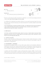
8.3 REMOVAL OF WINDING DRUM FOR MAINTENANCE 

NOTE:  Prior  to  commencing  the  steps  described  below,  disconnect  the  motor  cables  from  the  main  switch  to  prevent 

inadvertent  motor  actuating.  The  box  consists  of  fixed  part  (2)  and  removable  cover  (3).  If  it  is  necessary  to  remove  the 

drum, first remove two screws 

– one on each side – and remove the removable part of the box (3). If the motor used has a 

mechanical  end  switch,  the  switches  can  be  activated  by  a  screwdriver  through  tow  holes  (4)  pre-drilled  in  the  box  (on 

request). Specify the access position (from rear or front) when ordering. 


The roller blind components may vary in accordance with the roller blind dimensions and the motor type. The winding drum 

is attached to the side boards as follows: 


Summary of Contents for SCREEN LITE

Page 1: ...ed in the order form b attachment in front of an opening As a rule indicate the width of the opening which is to be shaded in the order form Dimensions outside the stipulated limits must be consulted with the manufacturer H height Measure the overall height including the roller blind upper section and holder DIMENSIONS OUTSIDE THE STIPULATED LIMITS MUST ALSO BE CONSULTED WITH THE MANUFACTURER COLO...

Page 2: ...depends of the model In case of outdoor installation if adverse weather conditions arise it is strongly recommended to draw the roller blind up to the box For motorised roller blinds it is recommended to use a wind sensor for the automatic roller drawing to the box 2 1 REQUIREMENTS FOR OPERATION All activities described for the installation maintenance and control of the motor end switches should ...

Page 3: ... Any intervention however small in the power supply requires a qualified electrician Faulty wiring faulty installation and any repairs adjustments or alterations made by any unauthorised personnel shall result in the loss of guarantee We recommend using solely original accessories and spare parts Our roller blinds are intended only for the use of original accessories DURING INSTALLATION Installati...

Page 4: ...lind function regularly Do not use the roller blind if maintenance is necessary 5 UNPACKING The SCREEN GW system is supplied partially assembled only the guide bars or cord accessories and ceiling brackets are packed separately After removing the packaging material check the roller blind for completeness and eventual visible damage to the components upper box guide bars etc If unsure do not use th...

Page 5: ...esponsible for defects caused by faulty installation 6 2 ROLLER BLIND INSTALLATION TO CEILING OR WALL Start the screen roller blind installation to the ceiling by marking out the attachment holes of the supporting brackets The distance of the screws from the roller blind edge should be 30 mm The screw spacing is 76 mm Leave a gap of at least 5 mm between the wall or ceiling and the supporting brac...

Page 6: ...table for the type of structure onto which they are to be attached metallic structure cement brick etc For front guide bar installation self adhesive covers are supplied to cover the attachment screw holes Once the installation is finished check parallelism and rectangularity of the guide bars This can be done by measuring two distances S1 and S2 or diagonals D1 and D2 The dimensions must be the s...

Page 7: ... D1 and D2 The dimensions must be the same 1 mm 6 5 EXTERIOR INSTALLATION WITH SLEEVE PASSING THROUGH WALL For exterior roller blinds installed with a sleeve passing through a wall and with a crank rod in the interior it is necessary to calculate the exact position of the hole for a 30 cm angular rod 15 Attach the brackets to a wall or ceiling and install the roller blind in its place Use a pencil...

Page 8: ...using a group control unit Do not use light switches Do not connect two or more switches to the same motor Do not use switches with blocking without a control unit for group control otherwise there is a risk of a duplicate command with consequent motor short circuiting Any damage caused by failure to comply with the above instructions shall not be attributed to the manufacturer and shall lead to a...

Page 9: ...nd and give this manual to the user for future reference NOTE There is a risk of compression in case a hand is trapped between the fabric and the upper box during the roller blind updrawing Before operating the roller blind move your hands outside of the movement range to prevent compression Vibrations or excessive noise indicate damage or faulty installation of the roller blind 8 2 TESTING To pro...

Page 10: ...your hands outside of the movement range to prevent compression Forced operation can cause damage to the roller blind 9 1 SAFETY DEVICES The motor includes a disconnecting overheating protection Thermal disconnection is activated after approx 4 6 minutes of continuous operation Before reactivating let the roller blind motor cool out Should you need assistance contact your dealer and ask for origin...

Page 11: ... not scrub by force OUTDOOR ROLLER BLIND SCREEN LITE DEFECT POSSIBLE CAUSE SOLUTION Fabric does not roll properly fabric side displacement Uneven fabric thickness manufacturing defect of the fabric Apply a distance layer e g adhesive tape directly onto the winding drum on the side opposite to where the fabric is moving Repeat applying further adhesive tape layers until the defect is completely rem...

Page 12: ... Increased noise Motor failure Disconnect the motor test it and replace if necessary Motor blocks after a long period of service The motor is in the thermal disconnection phase Wait for several minutes until the motor cools down NOTE Put the switch into neutral position to prevent its restart or uncontrolled operation Absolute absence of movement Improper wiring Check power supply at the switch Ch...

Reviews: