background image


©Isothermal Technology 

Page 61 of 61 

914 millisKanner manual Iss. 1.00 


11 Revision History 


Change Note 

Date 

Manual Issue 

Initial release 

28/02/2013 

1.00 

CN13105 

17/07/2013 

1.01 


Summary of Contents for millisKanner

Page 1: ...30 Fax 44 0 1704 544799 Internet Tel 44 0 1704 543830 Fax 44 0 1704 544799 Internet Tel 44 0 1704 543830 Fax 44 0 1704 544799 Internet www i www i www i www isotech co uk sotech co uk sotech co uk sot...

Page 2: ...1 Connecting Thermocouples using an ice point 24 3 5 2 Connecting Thermocouples using external compensation 25 3 5 3 Connecting Thermocouples using internal compensation 26 3 6 CONNECTING THERMISTORS...

Page 3: ...Liskanner STARt 53 8 2 6 11 Command MILLiskanner CLOSe 53 8 2 6 12 Command MILLiskanner OPEN 53 8 2 6 13 Command MILLiskanner RJC OFFSet 54 8 2 6 14 Command MILLiskanner RJC TEMPerature 54 8 2 6 15 Co...

Page 4: ...ing about how to control your multiplexer Each channel is provided with 5 binding posts for connection to a PRT or thermistor sensor with bare wire 4mm plugs or spade connections and a miniature therm...

Page 5: ...using the list of contents to find additional information as required 1 1 1 1 1 1 1 1 Unpacking Unpacking Unpacking Unpacking Your millisKanner product should comprise the following items millisKanne...

Page 6: ...ometer wires and therefore the binding posts and output connectors of the millisKanner becoming electrically live and therefore a hazard to the operator Suitable precautions should be taken such as us...

Page 7: ...ll cables and wires are routed safely to avoid tripping also to avoid sharp bends and pinches Clean only with a damp cloth Do not wet or allow moisture to penetrate the unit Do not use solvents See se...

Page 8: ...be daisy chained together The unused RS232 port on the last millisKanner in your system can be connected to a PC in order to control the whole measurement system using your own software see section 8...

Page 9: ...Iss 1 00 The binding posts accept 4mm plugs spades or bare wires The current I and voltage sense V terminals are spaced on 19mm centres so that standard BNC to 4mm adaptors not supplied can be used t...

Page 10: ...er the milliK software has initialised at the initial screen with the Start button or later press the Restart Update Software button on the Instrument screen of the milliK to re invoke the discovery p...

Page 11: ...ed worldwide If you need to connect to an outlet socket that is not supported by the plug heads provided you should source a suitable electrical supply lead locally that is fitted with a C8 connector...

Page 12: ...l modem cable provided see section 8 1 if you wish to make your own cable connect either of the RS232 ports on the millisKanner to either RS232 port on the rear of the milliK it does not matter which...

Page 13: ...Output Plug Colour Plug Colour Plug Colour Plug Colour Wire Colour Wire Colour Wire Colour Wire Colour V Black White V Red White I Black Red I Red Red Green Green N B You must use correct plug colour...

Page 14: ...ED below the terminal posts will light when measurements are being made on that channel If you want to control the measurement system milliK and millisKanner from a PC connect the unused RS232 port on...

Page 15: ...chain arrangement The RS232 ports on the millisKanner are completely interchangeable so it does not matter which is used to connect to the next millisKanner or the milliK in the system Similarly use...

Page 16: ...ent system milliK and millisKanners from a PC connect the unused RS232 port on the millisKanner at the end of the daisy chain to a PC using a null modem cable You can still communicate with the milliK...

Page 17: ...n 2 5 If you are controlling the millisKanner using the RS232 interface and making voltage measurements for thermocouples make two measurements with opposite polarity using CLOS POS and CLOS NEG comma...

Page 18: ...ir website www farnell com If a command is sent to the millisKanner to change channels it returns a CR carriage return when the change has been made Any software you write should take advantage of thi...

Page 19: ...ndicate which channel is selected When the millisKanner is connected to a milliK the left right buttons no longer operate because the milliK sends the REM see section 8 2 6 1 command to disable local...

Page 20: ...ctors between the millisKanner and the instrument does not operate This means that the voltage offset will be higher than when it is used with a milliK although it should be well within the 2 V specif...

Page 21: ...Connecting PRTs 4 Connecting PRTs 4 wire wire wire wire Your millisKanner is optimised for high accuracy 4 wire resistance measurement The PRT should be connected to the chosen input channel as follow...

Page 22: ...ther and then adding the single PRT lead to the binding post The top green terminal should be connected to the screen of the PRT s lead where present to minimise electrical noise picked up by the wire...

Page 23: ...ely the connections can use remote sensing using the 4 wire measurement capability of the milliK to eliminate the effect of lead resistance completely In this arrangement the current and voltage sense...

Page 24: ...ouple systems the most accurate thermocouple measurements are made with an ice point and the least accurate measurements are made with the internal reference junction compensation If the thermocouple...

Page 25: ...ct this to the socket below the binding posts Another temperature sensor PRT or thermistor must be used to measure the reference junction temperature ensure that it is isothermal with the reference ju...

Page 26: ...uple s reference junction 3 5 3 3 5 3 3 5 3 3 5 3 Connecting Thermocouples Connecting Thermocouples Connecting Thermocouples Connecting Thermocouples using using using using internal compensation inte...

Page 27: ...sociated with the internal reference junction sensor and any temperature gradients between the reference junction formed within each miniature thermocouple connector and the temperature of the referen...

Page 28: ...PRTs lead resistance is not normally a problem The top terminal should be connected to the screen of the thermistor s lead where present to minimise electrical noise picked up by the wires The high r...

Page 29: ...calibration of your millisKanner at one of our approved calibration centres contact Isothermal Technology or one of our appointed distributors for details The millisKanner should require little mainte...

Page 30: ...k satisfactorily with just a four wire connection to the PRT or thermistor it is better to use a screened cable and to connect the screen to the measurement ground terminal above the input terminals R...

Page 31: ...connected to the safety earth of the electrical supply Provide a clean electrical environment in your temperature laboratory It may be useful to filter your electrical supply into the laboratory espec...

Page 32: ...hen the readings are averaged together However this technique cannot be used when measuring the voltage generated by thermocouples so the thermal EMFs need to be eliminated at source For this reason w...

Page 33: ...instruments of this complexity is the contacts in switches relays connectors and potentiometers For this reason the millisKanner was designed to have no switches mechanical relays internal connectors...

Page 34: ...1 6 1 6 1 Before You Check the Calibration Before You Check the Calibration Before You Check the Calibration Before You Check the Calibration Any calibration should be performed in a temperature cont...

Page 35: ...rature and this is a reasonable choice However the error on a type J thermocouple even at 20 C might be 5 V or even higher which corresponds to a temperature error of approximately 0 2 C An alternativ...

Page 36: ...e RJC Sensor Calibration feature in the milliK to which it is attached Before you can use this feature you must first attach a calibrated thermocouple to one of the channels and configure the channel...

Page 37: ...00 keys to select the relevant channel and then use the keys to select each parameter in turn and press the key to enter their values Press the OK OK OK OK F4 key to start the calibration adjustment...

Page 38: ...e millisKanner to your PC using a null modem RS232 cable see section 8 1 Use Hyperterminal or another terminal emulator to connect to your millisKanner Hyperterminal is part of the standard Windows in...

Page 39: ...mware version in this case 1 00 so you can ensure that you wish to change this for the version you are about to install Send FIRM LOAD 1234 if password is still default value to put the millisKanner i...

Page 40: ...61 914 millisKanner manual Iss 1 00 When the firmware update is complete the millisKanner will report programming successful jumping to loaded application Now send IDN to confirm that the millisKanne...

Page 41: ...may be reversed without any impact on the operation of the system 8 1 8 1 8 1 8 1 Establishing an RS23 Establishing an RS23 Establishing an RS23 Establishing an RS232 Connection 2 Connection 2 Connec...

Page 42: ...Isothermal Technology Page 42 of 61 914 millisKanner manual Iss 1 00 1 2 3 4 5 6 7 8 9 Shell 1 2 3 4 5 6 7 8 Shell 9 Null Modem Cable A screened RS232 cable is recommended for minimum emissions...

Page 43: ...er is intended to be connected to and controlled by a milliK Precision Thermometer you can control it from a PC using your own software or Hyperterminal or another terminal emulator via the RS232 conn...

Page 44: ...ms that you have successfully established an RS232 connection with your millisKanner 8 2 8 2 8 2 8 2 SCPI Command Set SCPI Command Set SCPI Command Set SCPI Command Set The command format and protocol...

Page 45: ...tree structure Each node in the tree structure is a command keyword with keywords being separated by colons To simplify the description of the SCPI commands the notation represents levels in the tree...

Page 46: ...if the last letter is a vowel To indicate this the notation uses upper case to indicate required letters and lower case to indicate optional letters NB all commands are case insensitive For example va...

Page 47: ...2 4 Controlling Controlling Controlling Controlling the mi the mi the mi the milli lli lli llisKanner Using the RS232 Port sKanner Using the RS232 Port sKanner Using the RS232 Port sKanner Using the...

Page 48: ...e of a 4 wire PRT connected to the first input on the second millisKanner channel 20 on the 125 range at normal current 1mA the user can simply send the command MEAS RES20 125 NORM 4 This is identical...

Page 49: ...6 8 2 6 8 2 6 8 2 6 SCPI Commands SCPI Commands SCPI Commands SCPI Commands The millisKanner supports the following commands REMote LOCal IDN RST ROUTe CLOSe CLOSe OPEN ALL MILLiskanner LIST INITiali...

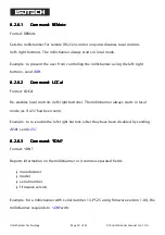
Page 50: ...2 6 2 8 2 6 2 8 2 6 2 Command LOCal Command LOCal Command LOCal Command LOCal Format LOCal Re enables local controls left right buttons The millisKanner always starts in local mode as if LOC had been...

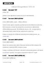
Page 51: ...ve NEGative parameter The millisKanner returns a CR carriage return to acknowledge that the channel has been selected and is ready to use Example to select the first millisKanner input with normal pos...

Page 52: ...anners serial numbers 13 P543 and 13 P544 firmware 1 00 connected in the daisy chain with a milliK serial number 13 P432 firmware 2 00 at the other end of the chain the response to MILL LIST will be I...

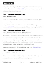
Page 53: ...mand MI Command MI Command MILLi LLi LLi LLiskanner CLOSe skanner CLOSe skanner CLOSe skanner CLOSe Format MILLiskanner CLOSe channel POSitive NEGative This command is reserved for use by the milliK a...

Page 54: ...RJC TEMPerature channel Reports the temperature of the reference junction in C for the specified channel Example a millisKanner assigned channel numbers 20 29 with a reference junction temperature of...

Page 55: ...he CAL UNL command see section 8 2 6 20 Example to set an offset that will be added to the RJC temperature sensor on the millisKanner to 0 321 C password still set to default value use CAL UNL 1234 fo...

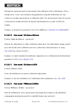
Page 56: ...ow calibration adjustment The millisKanner always powers up in the locked state Calibration can be re locked by cycling the power or using CAL LOCK see section 8 2 6 21 Example to unlock enable the ca...

Page 57: ...mal Technology Page 57 of 61 914 millisKanner manual Iss 1 00 Example to put the millisKanner which still has the default password 1234 into the mode that allows the firmware to be updated use FIRM LO...

Page 58: ...ut Connectors Connectors Connectors Connectors Binding Posts for 4mm plugs spades or bare wires Miniature thermocouple connectors contact material gold plated tellurium copper Interfaces Interfaces In...

Page 59: ...Grove Southport Merseyside PR9 9AG United Kingdom conforms to the requirements of the European Community Electromagnetic Compatibility Directive 89 336 and of the European Community Low Voltage Direct...

Page 60: ...the requirements for CE marking and for FCC compliance Conducted Emissions EN61326 2006 CFR47 2012 Radiated Emissions EN61326 2006 CFR47 2012 Conducted Immunity EN61326 2006 Radiated Immunity EN61326...

Page 61: ...Isothermal Technology Page 61 of 61 914 millisKanner manual Iss 1 00 11 Revision History Change Note Date Manual Issue Initial release 28 02 2013 1 00 CN13105 17 07 2013 1 01...

Reviews: