iSMA-B-W0202 User Manual
www.ismacontrolli.com
DMP263en | 1st Issue rev. 3 | 05/2022
page 10 of 41
•
•
•
•
•
•
•
4.3 Front Panel
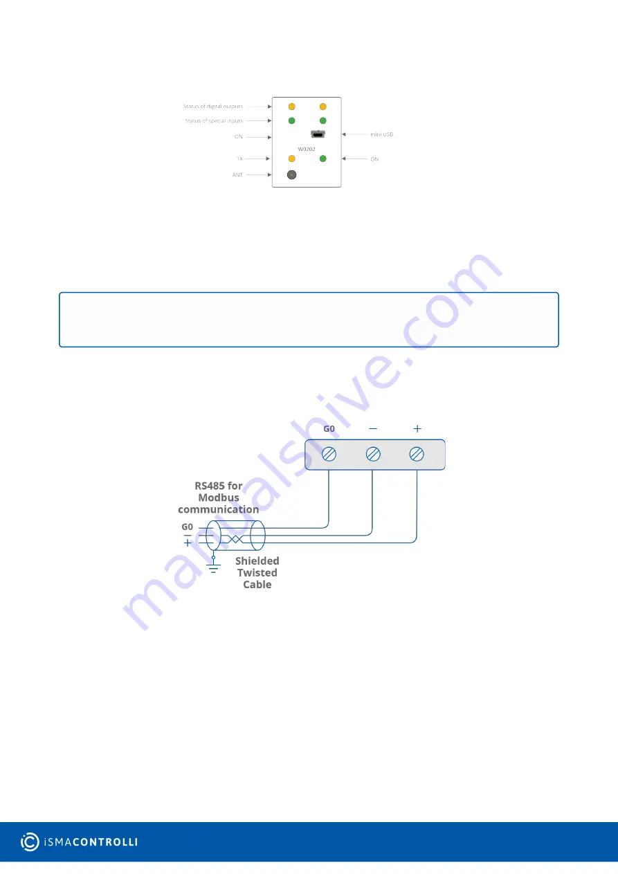
Figure 5. Front panel
The power LED (ON) is on (green) if the module is running properly;
The communication LED (TX) is on (orange) for 20 ms after sending each message. If
the module receives/sends a lot of messages, the LED can be lit continuously;
LEDs indicating the status of special inputs (S1-S2) are lit (green) if resistance
connected to the input is less than 1
kΩ
(dry contact input is active);
LEDs indicating the status of digital outputs (O1-O2) are lit (orange) if the output is
enabled.
4.4 RS485 Communication
Figure 6. RS485 connection
4.4.1 Grounding and Shielding
In most cases controllers are installed in enclosures along with other devices, which
generate electromagnetic radiation (for example, relays, contactors, transformers, motor
invertors, etc.). Such electromagnetic radiation can induce electrical noise into both
power and signal lines, as well as direct radiation into the controller, causing negative
effects on the system. For this reason, an appropriate grounding, shielding, and other
protective steps should be taken at the installation stage to prevent negative
electromagnetic radiation effects, for example:
control cabinet grounding;
cable shield grounding;
using protective elements for electromagnetic switching devices;
WARNING!
The LED also lights up if voltage connected to the input has a very low potential.


