Chapter 6 MECHANICAL ADJUSTMENT
UNI-5 Service Manual
6-3
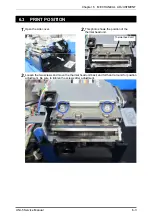
6.3 PRINT POSITION
1.
Open the side cover.
2.
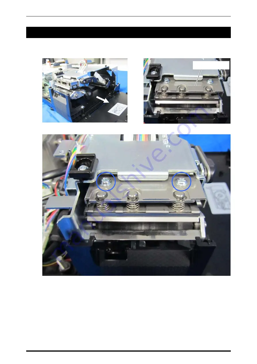
This photo shows the position of the
thermal head unit.
3.
Loosen the two screws and move the thermal head unit back and forth and around for position
adjustment. Be sure to tighten the screws after adjustment.
Thermal head unit
Summary of Contents for Uni-5
Page 11: ...Chapter 1 BASIC INFORMATION 1 2 UNI 5 Service Manual 1 1 2 OUTER DIMENSIONS FOR POLE TYPE ...
Page 12: ...Chapter 1 BASIC INFORMATION UNI 5 Service Manual 1 3 1 1 4 OUTER DIMENSIONS FOR ELEVATED TYPE ...
Page 16: ...Chapter 2 ASSEMBLY DRAWINGS UNI 5 Service Manual 2 1 ASSEMBLY DRAWINGS 2 1 BENCH TYPE 2 ...
Page 18: ...Chapter 2 ASSEMBLY DRAWINGS UNI 5 Service Manual 2 3 2 2 POLE TYPE ...
Page 22: ...Chapter 2 ASSEMBLY DRAWINGS UNI 5 Service Manual 2 7 2 5 PRINTER FOR EACH TYPE ...

