Chapter 5 MACHINE DISASSEMBLY
5-10
UNI-5 Service Manual
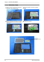
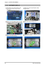
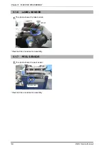
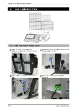
5.1.9
LOAD CELL & A/D BOARD
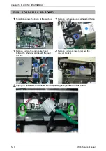
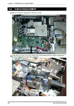
1.
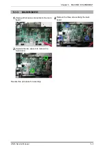
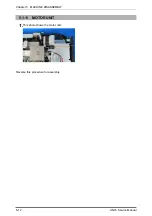
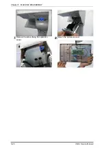
This photo shows the inside of the machine.
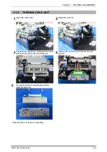
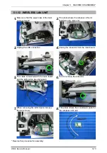
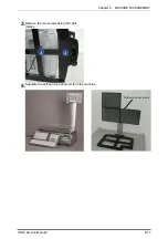
2.
Remove the hexagon socket head bolt fixing
the load cell unit.
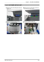
3.
Remove the two hexagon socket head
bolts at the other end and detach the load
cell unit.
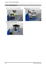
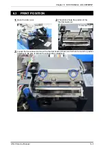
4.
Remove the two screws to remove the
die-cast bracket.
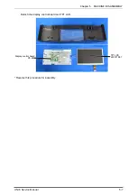
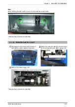
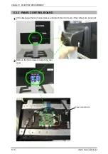
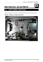
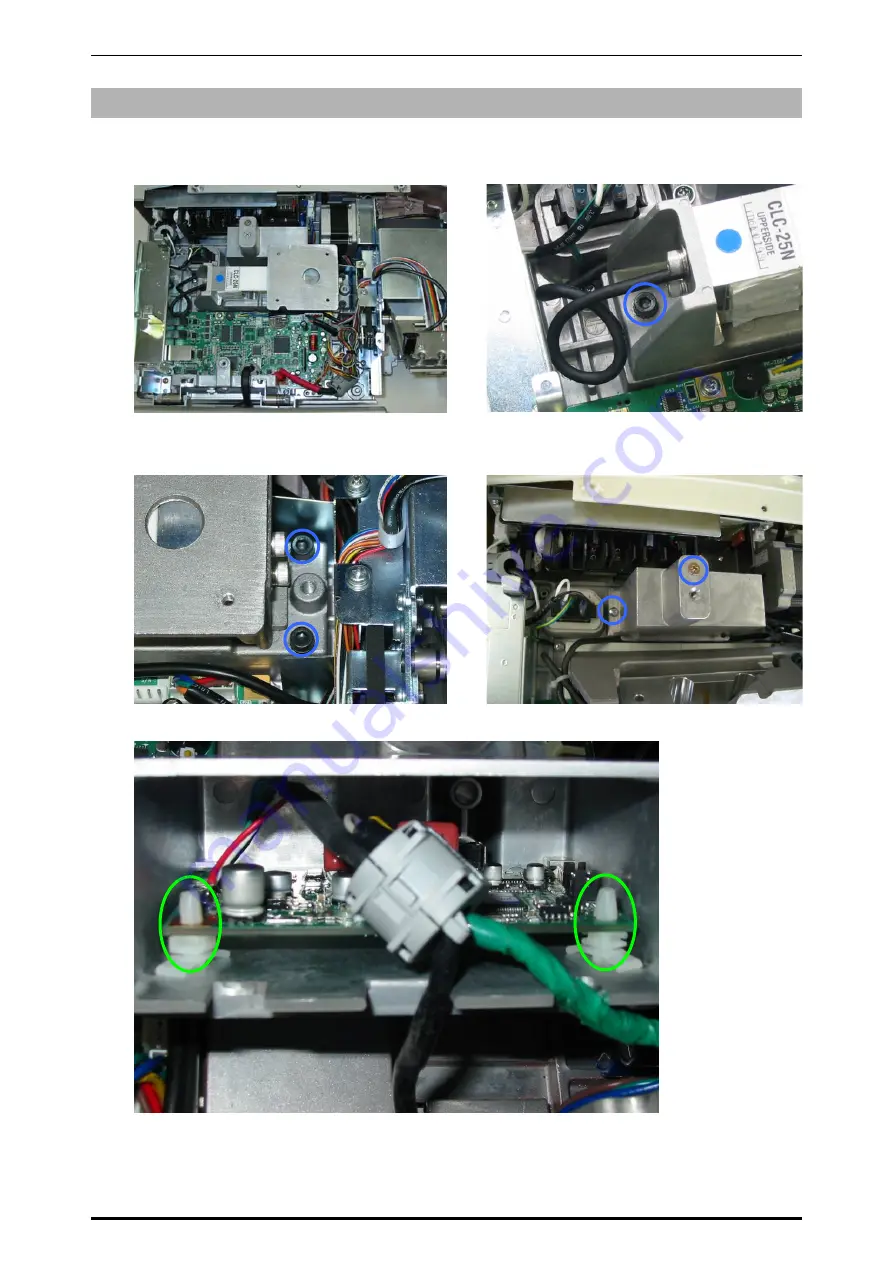
5.
Unplug the harnesses and squeeze the two spacers (green) to detach the AD board.
Summary of Contents for Uni-5
Page 11: ...Chapter 1 BASIC INFORMATION 1 2 UNI 5 Service Manual 1 1 2 OUTER DIMENSIONS FOR POLE TYPE ...
Page 12: ...Chapter 1 BASIC INFORMATION UNI 5 Service Manual 1 3 1 1 4 OUTER DIMENSIONS FOR ELEVATED TYPE ...
Page 16: ...Chapter 2 ASSEMBLY DRAWINGS UNI 5 Service Manual 2 1 ASSEMBLY DRAWINGS 2 1 BENCH TYPE 2 ...
Page 18: ...Chapter 2 ASSEMBLY DRAWINGS UNI 5 Service Manual 2 3 2 2 POLE TYPE ...
Page 22: ...Chapter 2 ASSEMBLY DRAWINGS UNI 5 Service Manual 2 7 2 5 PRINTER FOR EACH TYPE ...