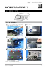
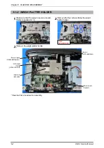

Chapter 5 MACHINE DISASSEMBLY
UNI-5 Service Manual
5-9
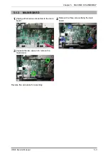
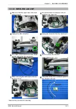
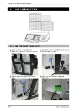
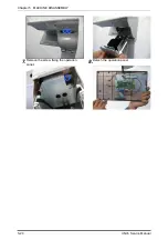
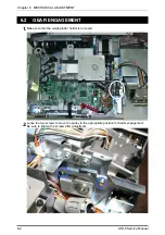
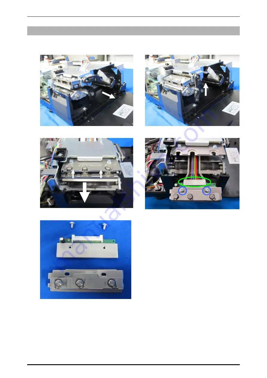
5.1.8 THERMAL
HEAD
UNIT
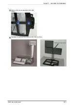
1.
Open the side cover.
2.
Raise the lock bar.
3.
Squeeze the springs by holding up the head
unit and pull out the thermal head unit.
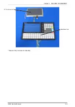
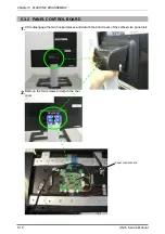
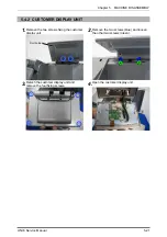
4.
Unplug the connector and remove the two
screws.
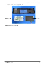
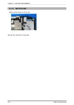
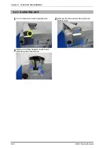
5
This photo shows the breakdown of the
thermal head unit.
* Reverse this procedure for assembly.
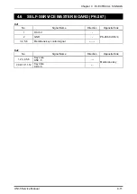
Summary of Contents for Uni-5
Page 11: ...Chapter 1 BASIC INFORMATION 1 2 UNI 5 Service Manual 1 1 2 OUTER DIMENSIONS FOR POLE TYPE ...
Page 12: ...Chapter 1 BASIC INFORMATION UNI 5 Service Manual 1 3 1 1 4 OUTER DIMENSIONS FOR ELEVATED TYPE ...
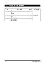
Page 16: ...Chapter 2 ASSEMBLY DRAWINGS UNI 5 Service Manual 2 1 ASSEMBLY DRAWINGS 2 1 BENCH TYPE 2 ...
Page 18: ...Chapter 2 ASSEMBLY DRAWINGS UNI 5 Service Manual 2 3 2 2 POLE TYPE ...
Page 22: ...Chapter 2 ASSEMBLY DRAWINGS UNI 5 Service Manual 2 7 2 5 PRINTER FOR EACH TYPE ...