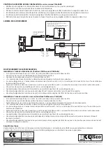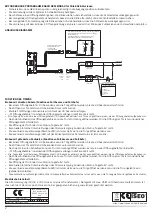
GENERAL OPERATING CHARACTERISTICS
Anti-panic/emergency type lock (see pre-set articles) that can be combined with a panic exit bar/handle on the inner side and a
handle plate on the outer side. From the inner side, the panic exit bar/handle (see pre-set articles) opens the door, regardless of the
power supply to the lock or the throw mechanism position.
The handle can only be opened from the outer side if:
the lock is electrically powered and the “impulse” or “hold-open” opening command is given
the power supply to the lock is disconnected (only for articles with the Fail-Safe function)
the key has brought the throw mechanism back (ATTENTION: the electronic functions are only activated when the handle is
disabled)
Operating temperature -20°C +70°C
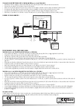
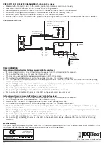
CONNECTION AND ELECTRIC CHARACTERISTICS
Set up the electric system in accordance with the regulations in force.
Make sure the electric system is disconnected from the mains supply before connecting the cables and/or carrying out any other
interventions.
Before making the connection, check that the output voltage of the power supply unit is equal to the rated voltage value
required, and that the power is at least equal to the value required.
Power the lock at 12V-24V AC/DC +/-10%
Max current absorption 350 mA
Input command for opening 12V-24V AD/DC +/-10% 10mA
Input/Output supply cable L=7m 4 poles
to be ordered separately
art. 0000A00039
.
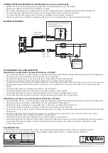
Preparation for a possible remote LED (not supplied) 12V-24V AC/DC +/-10% with max current absorption 10 mA for the remote
signalling of lock activation/deactivation.
Preparation of lock status signalling for possible red and green LEDs on the handle plate (not supplied).
Built-in timer with fixed time 30 sec +/-5 sec, with possible automatic reset (time reset) after every door opening if fitted with
sprung electric contacts.
“Hold-open” function.
In the case of an AC supply, the cables have no polarity.
In the case of a DC supply and the use of a remote LED, respect the cable polarities indicated in the diagram.
Use cables with a section no less than 1 sq.mm
Make sure the wires are not laid close to sharp edges.
Make sure that the recess for mounting the lock has no sharp or protruding parts which could damage the insulation of the
external cables of the lock.
After making the connection, check there are no short-circuits.
INSTALLATION
Make sure the screws for fixing the bar and handle plates don't interfere with the lock.
Before fitting the handle, check it rotates freely (without jamming).
Make sure the spindle length is suitable for the thickness of the door.
Make sure the cylinder length is suitable for the thickness of the door.
CHECKS TO BE MADE AFTER INSTALLATION for FAIL-SECURE versions
Make sure the handle(s) returns to the starting position spontaneously and simultaneously.
Activate the throw mechanism with the cylinder in the closing direction.
Send an opening command to the lock, then turn the handle and check that the latch is recalled.
Without any opening command, check the handle rotates freely without recalling the latch.
Without the power supply, check the handle rotates freely without recalling the latch.
Eliminate the throw mechanism with the cylinder in the opening direction, then use the handle to check the latch is recalled.
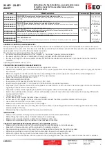
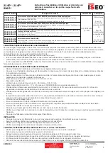
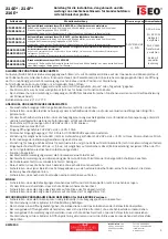
Art. code.
Model description
Power supply
Current absorption
FAIL SECURE fire panic locks that can be combined with panic exit bars.
Outer side: latch operated by key and handle (only if enabled by the key or electromagnet) (FAIL
SECURE).
Inner side: (anti-panic side) latch operated by bar or key.
12/24 Vac/dc
+/- 10%
max 350 mA
10W power
supply unit
recommended
for DC
24VA
transformer
recommended
for AC
both double
insulated
FAIL SAFE fire panic locks that can be combined with panic exit bars.
Outer side: latch operated by key and handle (only if enabled by the key or by the lack of power supply)
(FAIL SAFE).
Inner side: (anti-panic side) latch operated by bar or key.
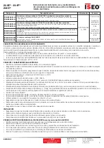
instructions for the installation, use and maintenance
of mortice locks for fire-resistant doors with an
electronic card.
214E* - 214F*
216E*
1
Iseo Serrature
s.p.a.
Via San Girolamo 13
25055 Pisogne (
)
BS
Italy
Tel +39 0364 8821
Fax +39 0364 882263
[email protected]
www.iseo.com
KW14150
FAIL SECURE emergency fire locks with reversed latch for internal opening, which can be
combined with the internal emergency handle.
Outer side: latch operated by key and handle only if enabled by the key or electromagnet (Fail Secure).
Inner side: (emergency side) latch operated by handle or key.
FAIL SECURE fire lock
Inner / Outer side: latch operated by key and handle only if enabled by the key or electromagnet (Fail
Secure)
214E10654..D
214E10654..S
214F10654..D
214F10654..S
214E10654.CD
214E10654.CS
216E30654.5D
216E30654.5S


