iCU-DC / iCU-EC Operating Instructions
Page - 17
➈
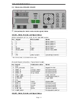
AC Input
–
115/230 VAC, 50 …60 Hz
The power input module includes these components: appliance connector socket,
filter, fuse holder, fuses and power switch. The supplied power cable must be
connected with the appliance connector socket and the power socket before
initialisation. After that, the controller can be switched on using the main switch.
!
Neutral Conductor Fuse !
➉
Spindle
-115V/ 230V connection
Here at this output, you can directly connect a milling spindle without RPM control if
you use the supplied mating plug. Maximum switching at the relay output is
115V/230VAC / 6A. The signal for the spindle to start (24V) is switched via
the CAN I/O module, analysed via the SK module (iSM5), and then the power supply
of 115/230V is switched to the working spindle (e.g. UFM 500, 750, 1050) via a
relay.
Take note of the CAN I/O module table defining assigned spindle start
signals, in section 4.2.
⑪
Connection for main spindle drive (optional)
Here at this connection, a processing spindle with RPM control is attached
(asynchronous motor). The (optional) frequency converter is located in the controller
and is operated via the safety circuit and I/O module.
Pin
Name
1
Motor phase U
4
Motor phase V
3
Motor phase W
PE
PE
A
-
B
-
C
Fan 230V AC-L
D
Fan 230V AC-N
Housing
⑫
Ethernet connection for the integrated control computer, IPC15
1x RJ45 socket for network integration (100MBit, LAN, Ethernet)
⑫
VGA connection for the integrated control computer, IPC15
15 pole connection socket for a VGA monitor
⑭
USB 2.0 connections
USB devices (data sticks, external CD/DVD drives) can be connected to these
sockects.


