iCU-DC / iCU-EC Operating Instructions
Page - 16
➆
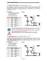
Digital electrical outputs
- 8 pole, left to right A1.1
–
A1.4
The installed I/O component group has two digital output ports, each with eight
digital switching outputs. The first output port (A1.1 - A1.8) is already partially wired
internally and occupied by switching outputs. The outputs A1.1 - A1.4 may be
assigned by the user.
Properties
- 4
x digital electronic outputs
-
Imax < 350mA, 24VDC
-
Thermal protection
-
Short-circuit protection
Wiring
Pin
Output
Name
1
Out1
Output A1.1
2
GND
GND
3
Out2
Output A1.2
4
GND
GND
5
Out3
Output A1.3
6
GND
GND
7
Out4
Output A1.4
8
GND
GND
Note the default assignment of the first output port (A1.1 - A1.8) when
setting the “signalling” in the user interface Remote / ProNC.
The outputs
A1.5 - A1.8 are already wired inside the controller to their modules and
can no longer be used by the operator!
When using intuctance, an free-wheeling diode is necessarily.
➇
Digital Relay Outputs
- 8 pole, left to right A2.1
–
A2.4
The installed I/O component group has a second digital output port, with four more
digital
relay switching outputs
. The second output port (A2.1 - A2.8) is already
partially wired internally and occupied by switching outputs. The outputs A2.1 - A2.4
may be assigned by the user.
Properties
- 4
x digital relay outputs
-
Imax < 5 A, 24VDC
-
Thermal protection
-
Short-circuit protection
Wiring
Pin
Output
Name
1
Out1
Output A2.1
2
GND
GND
3
Out2
Output A2.2
4
GND
GND
5
Out3
Output A2.3
6
GND
GND
7
Out4
Output A2.4
8
GND
GND


