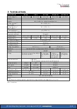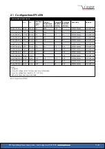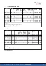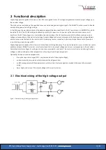
3.5 Analogue I/O interface (AIO)
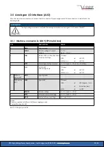
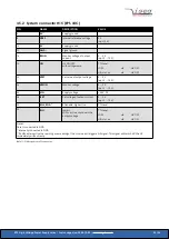
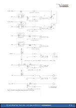
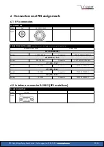
All control inputs and outputs are located at the AIO connector. The pin assignment of these connectors is described in the
following table.
INFORMATION
INFORMATION
The high voltage is turned on/off with the analogue interface control signals “ON” and/or “INHIBIT”.
3.5.1 Interface connector D-SUB 9 (EPS metal box)
PIN
DESCRIPTION
VALUE
1
GND
Signal ground
2
IMON
Monitor voltage of output
current
0 ... 5 V
(opt. 0 ... 10 V)
1)
3
INH
Inhibit, LOW = active, shut down
the output voltage
TTL-level:
LOW
➜
HV OFF
HIGH or n.c.
➜
HV ON
4
ISET
Set voltage of output current
0 ... 5 V / (opt. 0 ... 10 V)
(1
, R
i
= 10 MOhm
5
ON
HV ON/OFF
with voltage ramp
TTL-level:
LOW
➜
HV ON
HIGH or n.c.
➜
HV OFF
6
Without
option ARC
GND
Signal ground
With option
ARC
/ARC
Signal ARC
TTL level:
LOW
➜
ARC (approx. 1 ms)
➜
INH active (low)
HIGH
➜
no ARC
7
VMON
Monitor voltage
0 ... 5 V / (opt. 0 ... 10 V)
(1
8
VSET
Set value of output voltage
0 ... 5 V / (opt. 0 ... 10 V)
(1
9
VREF
Internal reference voltage
5 V / (opt. 10 V)
(1
Notes:
Case is connected to GND and 0V (Power supply ground)
1)
only without option ARC
Table 10: PIN Assignment D-SUB 9
EPS High Voltage Power Supply series | Last changed on: 2020-12-02 |
www.iseg-hv.com
22/36


