3.6 Connector assignment
3.6.1 DC Supply, metal box
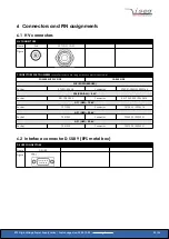
The device is connected to a DC power supply using the 2 screw terminals on the front of the device (maximum connection cross
section 2.5 mm²), which are marked with 0 V or +24 V.
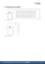
Devices of the 150 W class are equipped with a threaded bolt marked with protective conductor (thread M4). This bold must be
connected to the external protective conductor system (PE) or the local equipotential bonding system.
3.6.2 DC Supply, 3UC
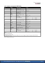
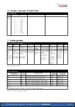
The device is connected to a DC power supply using the H15 connector at the corresponding pins (0 V and V
IN
, see Table 11: PIN
3.6.3 High voltage connection
The device has one high voltage output.
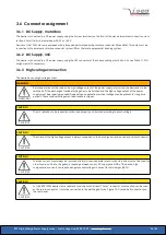
WARNING!
WARNING!
Before operations at the load or the high voltage output of the power supply are started, the device has to be
switched off, the discharge of residual voltage has to be finished and the high voltage output of the power
supply must be properly grounded. Depending on application residual voltages can be present for long time
periods. These residual voltages can lead to severe injuries.
CAUTION!
CAUTION!
The HV cable has to be connected to the load properly and isolated according to proof-voltage.
CAUTION!
CAUTION!
The shield of the high voltage output is always connected to the housing and can be used as a return conductor.
CAUTION!
CAUTION!
The load current must always be returned directly (screen, separate return conductor) and must not be used for
other functions. Due to the galvanic coupling between control, DC supply and GND of the device, high
compensation currents can lead to dangerous overvoltages in case of fast discharges (ARCs).
CAUTION!
CAUTION!
For the EPS 150W device class a separate conductor with at least 1.5 mm
2
conductor cross-section can be used
as the return conductor. It must be connected to the earthing bolt (see Figure 10: Ground bolt connection) on
the rear panel.
EPS High Voltage Power Supply series | Last changed on: 2020-12-02 |
www.iseg-hv.com
26/36


