jcb 929/05400, Service Manual
The JCB 929/05400 Service Manual is the essential resource for maintaining and troubleshooting your equipment. Download this comprehensive manual for free from manualshive.com, providing you with step-by-step instructions and expert guidance. With easy access to this user-friendly manual, you can ensure the optimal performance of your JCB 929/05400.
Share
Download


Reviews:
No comments
Related manuals for 929/05400
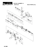
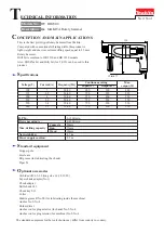
HR2450 Series
Brand: Makita Pages: 5
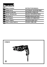
HR2230
Brand: Makita Pages: 40
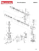
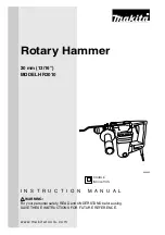
HR2010
Brand: Makita Pages: 3
HR2010
Brand: Makita Pages: 16
HR2000
Brand: Makita Pages: 6
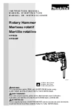
HR1830F
Brand: Makita Pages: 28

VisionXS-IP-F-DP-UHR
Brand: G&D Pages: 148

Performance IntelliSUPPLY PSC15
Brand: XS Power Batteries Pages: 24

ST400 STRIDER
Brand: SilverStone Pages: 12

ELK-P412
Brand: Elk Products Pages: 2

CV-E
Brand: jbc Pages: 72

SLZ 07
Brand: Sanela Pages: 2

MIG-HMP50
Brand: Solaric Pages: 16

10534047
Brand: Wolf Garten Pages: 198

054-6988-6
Brand: MasterCraft Pages: 30

BPU 2540A
Brand: Wacker Neuson Pages: 40

MPV2200-75
Brand: BRICK Pages: 30

GSH25-C1
Brand: P.I.T. Pages: 20


