background image

Ironwood JT400  |  User Manual

16

To remove and replace inserts, proceed as follows: 

1. Loosen the knife gib by turning the Allen head screw in the

knife gib.

2. Remove the knife gib and knife.

3. Remove the remaining knives in the same manner.

4. Thoroughly clean the knife slots and knife gibs.

5. Check the screws. If they appear worn or stripped, replace

them.

6. In sequence, insert the knife and knife gib into the slot of the

cutterhead.

7. Fasten knife and gib with a spacer and Allen head screw.

8. Repeat the process until all knives are set in position and tight.

Step 3:

 Align and Adjust Outfeed Table 

 Caution

The proper outfeed table height is preset at the factory. To ensure 
the setting did not change during shipping, check outfeed table 
height before you use the machine for the first time. Re-check 
periodically.

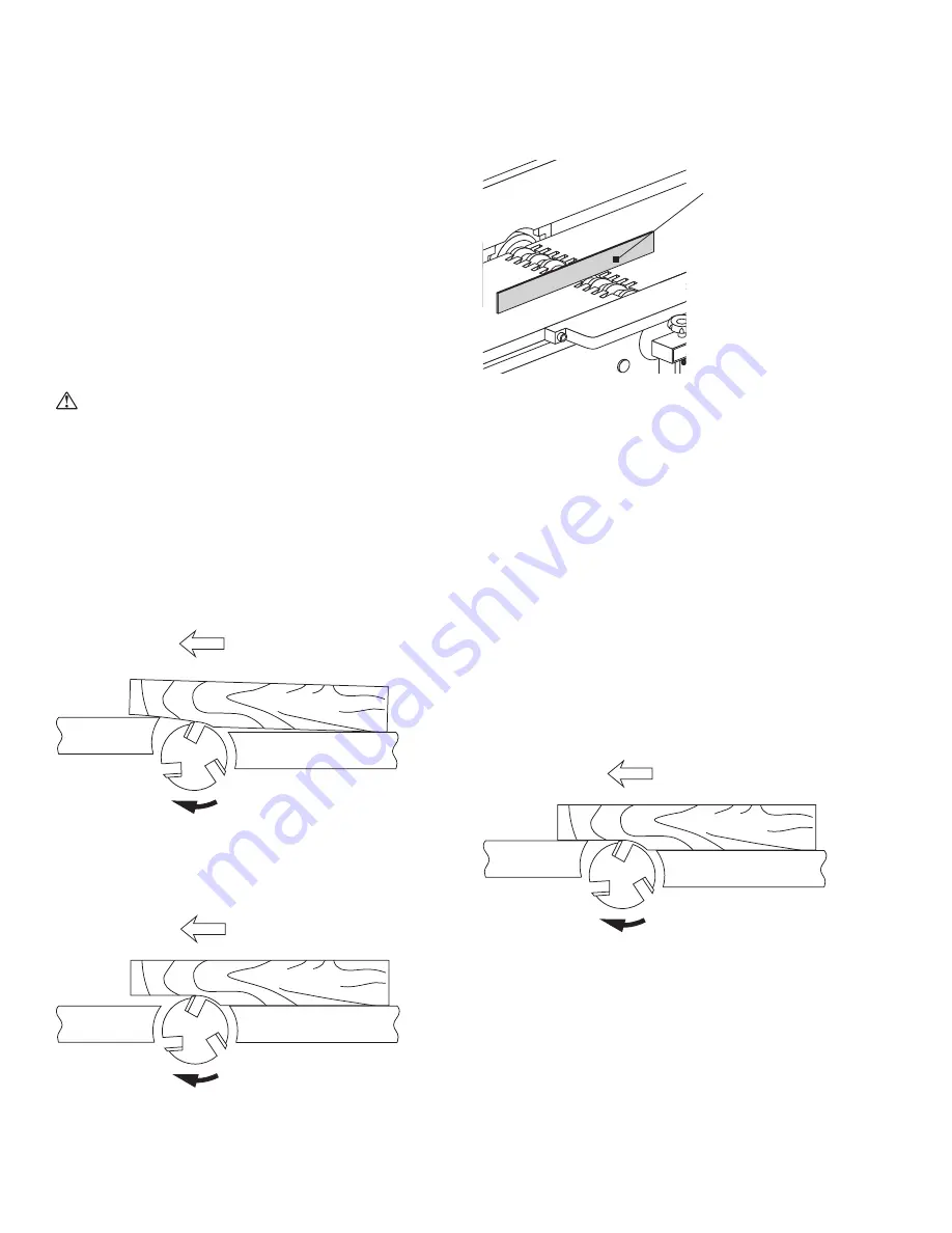
For accurate work in most jointing operations, the outfeed table 
must be exactly level with the knives at their highest point of 
revolution. 

If the outfeed table is too high, the finished surface of the workpiece 
will be curved.

Work Piece

Infeed Table

WRONG

Outfeed Table

Cutter

Head

If the outfeed table is too low, the work will be gouged or sniped at 
the end of the cut. 

Work Piece

Infeed Table

Outfeed Table

Cutter

Head

WRONG

To properly align the cutterhead with the outfeed table:

1. Place a straight edge on the outfeed table and over a knife

tip on the cutterhead. Be careful not to damage the carbide
inserts.

Verify blade height
with straight edge.

2. Carefully turn the cutterhead by hand.

•  If a knife tip makes contact with the straight edge, but

the straight edge does not move, the outfeed table is set
properly.

•  If a knife tip does not touch the straight edge, the outfeed

table is too high.

•  If the straight edge lifts slightly when knife makes contact,

the table is set too low.

To adjust the outfeed table height:

1. Loosen the table lock lever.

2. Move the adjustment handle up or down.

3. Tighten the table lock lever.

As a final check, run a piece of wood slowly over the knives for 6 to 
8 inches. The wood should rest firmly on both tables with no open 
space under the finished cut.

Infeed Table

Outfeed Table

Cutter

Head

Work Piece

CORRECT

Summary of Contents for JT400

Page 1: ...ance cutterhead maintenance blade care periodic maintenance troubleshooting electrical print facility preparation connect to power safety delivery and installation inspection pre operation cleaning as...

Page 2: ...e Machine from Pallet 3 6 Level 3 7 Pre Operation Cleaning 4 0 Connect to Power 11 5 0 Safety 12 6 0 Assembly 13 6 1 Fence Assembly 6 2 Dust Collection Manifold 6 3 Cutterhead Guard 7 0 Operation and...

Page 3: ...on the metallic plate Machine information plate Stiles Technical Support 616 698 6615 Stiles Parts 800 PARTS 80 800 727 8780 Website www stilesmachinery com ironwood jt400 Machine Model_______________...

Page 4: ...mm Fence Size 47 x 5 5 1 195mm x 140mm Fence Tilt 45 degrees Positive Stops 45 90 135 degrees Cutterhead Speed 5 000 rpm Number of Knives 60 Cutterhead Insert Size 30mm x 12mm x 1 5mm Cutting Circle 5...

Page 5: ...achinery immediately for replacements Label 1 Safety Rules LABEL NO 1 WARNING Never use the JT400 for purposes other than its intended use Do not modify or remove any guards or other safety features I...

Page 6: ...vary depending on length of material to be cut 2 3 Power WARNING A licensed electrician must connect the JT400 to the building power source Do not use extension cords Be sure that the electrical curre...

Page 7: ...ck or fork lift to move the machine on its pallet as close to its final position as possible If you do not intend to install the machine immediately after delivery store it in a protected cool and dry...

Page 8: ...ers to ensure all tools hardware and accessories are included The tool kit should contain the following items 1 4 piece open end wrench set 2 4mm 5mm 6mm and 8mm short handle Allen wrenches 3 5mm long...

Page 9: ...bolts that secure the machine to the pallet at the interior corners 2 Lift the machine from the pallet by one of 3 methods a Team lift b Slide machine onto forks of fork lift c With a fork lift or cr...

Page 10: ...ot use gasoline or other petroleum based solvents There is a risk of explosion and burning if these products are used Serious personal injury may occur The machine is shipped with protective paper on...

Page 11: ...power switch is off Proper wiring inside terminal box To connect power source to the machine 1 Remove the two screws and remove the terminal box cover 2 Remove the clear plastic insulator that covers...

Page 12: ...c Code and local regulating authorities GUARDS Make certain that machine guards are in place and in good working order The machine should never be operated without safety guards in place TOOLING AND A...

Page 13: ...mbly to the machine body at the two holes using the provided cap screws and lock washers Fence Cap screw and lock washer Hole locations 6 2 Dust Collection Manifold PARTS REQUIRED Dust collection mani...

Page 14: ...ng away guard The interchangeable cutterhead guard protects your hands and helps guide the cut There are two styles of guards available on the JT400 jointer The fold away guard comes standard with the...

Page 15: ...s on the threaded rods in place They keep the belt cover from bending during tightening 2 Loosen the lower hex nut on the motor base with an Allen wrench 3 Turn the top hex nut clockwise until proper...

Page 16: ...o high the finished surface of the workpiece will be curved Work Piece Infeed Table WRONG Outfeed Table Cutter Head If the outfeed table is too low the work will be gouged or sniped at the end of the...

Page 17: ...onfirm table height To check table height 1 Place a straight edge on the infeed table and over a knife tip on the cutterhead Be careful not to damage the carbide inserts Verify blade height with strai...

Page 18: ...e surface 4 If the angle is not 45 degrees loosen the hex nut on the stop screw 5 Turn the stop screw until the fence is flush with the protractor 6 Tighten the hex nut 7 Tighten the lock handle Step...

Page 19: ...t is entirely fed through the machine press the Off button Wait until the cutterhead has completely stopped before removing material Attempted removal while cutterhead is turning may cause kickback To...

Page 20: ...e pressure prevents the jointer from flattening the workpiece so it remains warped curved or cupped Jointing Short or Thin Workpieces Always use a push block to prevent injury when jointing short or t...

Page 21: ...n and dry them 8 2 Inspection FEATURE INTERVAL SITUATION Cutterhead Daily Belt Every week for the first 3 months and monthly thereafter Emergency stop Daily by functional test Safety guard Daily Elect...

Page 22: ...damage and replace as necessary 8 5 Periodic Maintenance It is important to clean the inside of the machine daily to help ensure long machine life and superior performance Take care to prevent dust fr...

Page 23: ...ctions in wood Cut with the grain whenever possible Replace inserts Use slower rate of feed Make shallower cuts Inspect wood closely for imperfections use different piece of wood if necessary Fuzzy gr...

Page 24: ...Ironwood JT400 User Manual 24 9 1 Electrical Print...

Page 25: ......

Page 26: ...Stiles Machinery Inc 3965 44th St SE Grand Rapids MI 49512 p 616 698 7500 f 616 698 9411 www stilesmachinery com 2013 Stiles Machinery Inc Version A September 2013...

Reviews: