background image

CM-IW2000 Instruction Manual

3

Installation Preparation

The CM-IW2000 features an integral Roto-Lock

®

 mounting system 

for quick mounting directly into existing walls. Once the hole is cut 
and  the  cables  have  been  run,  you  can  install  the  iPort  into  the 
wall in a matter of seconds.
1.  Determine  the  location  for  the  iPort  Control  Mount  and  the 

wall plate. 

2.   Perform  an  obstruction  survey  to  ensure  there  are  no  studs, 

conduit, pipes, heating ducts, or air returns that will interfere 
with the Control Mount.3.  

Find  the  cut-out  template 

provided  in  the  CM-IW2000  packaging.  Place    in  appropriate 
location between wall studs. Verify there are no horizontal fire 
blocks with-in cut out area. Place level on template to assure a 
level opening. Position the template where the Control Mount is 
to be located and pencil an outline on the wall. 

•  If you are unsure about obstructions, drill a small hole in the 

center of the outline and insert a coat hanger wire into the 
hole to feel around for possible obstructions.

4.   Cut the opening using a drywall saw.
5.  After cutting the opening, make sure the edges of opening are 

smooth so frame flange will rest flat against wall.

iPort Connection and Installation

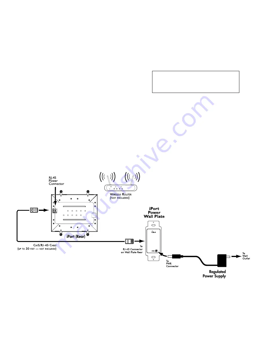
See Figure 3

1.   Before making connections, run a length of Cat5 cable through 

the wall from the Control Mount location to the power wall plate 
location, as shown in Figure 3. The wall plate can be located up 
to 30 feet from the control mount.

2.   Install  RJ-45  connectors  on  both  ends  of  the  Cat5  cable  as 

explained in Figure 2: Cat5 / RJ-45 Power connector. The  Cat5/
RJ-45 cable pin assignment is:

3.   Plug the Cat5 cable into the RJ-45 jack on the Control Mount 

and the RJ-45 jack on the wall plate, as shown in Figure 3.

4.   Install the wall plate into an electrical box 

2

1

3

4

POWER

INTERNET

WIRELESS

 ETHERNET PORT

To Audio
Wall Plate

CM-IW100T

®

U.S. Patent No. 7,493,142

Additional Patents Pending

Designed and Engineered in the USA

33-5203   4-09

Pin 1:  

Unused

Pin 2: 

Unused

Pin 3: 

Unused

Pin 4: 

Unused

Pin 5: 

Unused

Pin 6: 

Unused

Pin 7: 

Ground

Pin 8: 

+15V

Figure 3: iPort System Connections

Summary of Contents for CM-IW2000

Page 1: ...Control Mount Instruction Manual CM IW2000 ...

Page 2: ...n The CM IW2000 features an RJ 45 jack to connect to the powered wall plate via Cat5 cable The power connection receives DC power through the RJ45 connector as shown in figure 1 Wiring Cat5 RJ 45 Cable The Cat5 cable and RJ 45 connector used in iPort installations must be wired according to the T568A Straight Through Standard with cables wired identically at both ends To prepare the Cat5 cable and...

Page 3: ...oat hanger wire into the hole to feel around for possible obstructions 4 Cut the opening using a drywall saw 5 After cutting the opening make sure the edges of opening are smooth so frame flange will rest flat against wall iPort Connection and Installation See Figure 3 1 Before making connections run a length of Cat5 cable through the wall from the Control Mount location to the power wall plate lo...

Page 4: ...mounting frame as shown in Figure 5 The Roto Lock clamps will automatically rotate into position behind the wall and begin clamping the mount When you notice resistance on the four screws the Control Mount has been clamped successfully Important NEVER over tighten the Roto Lock screws 8 Mount iPad to the bezel by placing iPad into nesting area on rear of bezel and attach metal retainer with ten 10...

Page 5: ...al frame 12 Connect the Cat5 cable from the wall to the iPad connector board as noted in figure 8 Final Adjustment 1 Mounting frame is supplied with a preset height setting The preset adjustment will likely result with a space between the bezel and the wall surface To adjust the height setting turn screws clockwise one turn at a time until bezel fits snugly against the wall as shown in figure 9 2 ...

Page 6: ...e used as guidelines to achieve a custom finish A light coat of paint to match the surrounding wall is recom mended A light coat will allow the bezel to maintain all proper tolerances and ensure precision fit Do not roll or brush paint onto the bezel 1 Apply a light coat of XIM Primer Bonder or similar to the bezel Carefully follow the directions on the can NOTE Match the primer type to the specif...

Page 7: ... regulated Dimensions W x H x D 11 60 x 9 51 x 2 36 294 6mm x 241 6mm x 59 9mm Cut out Dimensions W x H 10 75 x 8 65 273 1mm x 219 7mm 11 60in 294 6mm 9 51in 241 6mm 10 75in 273 1mm 8 65in 219 7mm 1 49in 38mm 2 36in 59 9mm 0 24in 6 1mm 10 75in 273 1mm 8 65in 219 7mm ...

Page 8: ... CM IW2000 Warranty Period for this Product One 1 year from the date on the original sales receipt invoice or other satisfactory proof of purchase Additional limitations and Exclusions From Warranty Coverage The warranty described above is non transferrable and does not include damage to allied or associated equipment which may result for any reason from use with this Product and does not include ...

Reviews: