


OPTIDRIVE elevator
| Quick Start-up Guide | Version 1.0
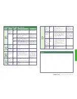
Optimising & improving travel comfort
Symptom
Possible
Cause
Control
Modes
Possible Corrective Actions
Notes
1 –
Rollback
During
starting
Brake
release time
maybe too
short.
P
4-01 =
0-3
Increase
P
3-07 (Brake Release time)
P
2-02 (HighSpeed)
P
4-01 =
0,1,2
Increase
P
4-03 (Speed Controller
P-Gain)/ decrease
P
4-04 (Speed
Controller I-Gain)
Higher value=faster
response/ Eliminates
steady state speed
error.
P
4-01 =
0,1,2
If Modifying
P
P4-03/
P
4-04 is not
successful use Closed loop (With
Encoder)
P
4-01 = 2 If Modifying
P
4-03/
P
4-04 is not
successful Increase value in parameter
P
1-11 (V/F Mode Voltage Boost).
Take care when
modifying Increasing
too high could
overheat the motor
1 –
Jerk Felt
During
starting
Brake not
releasing
quick
enough
P
4-01 =
0,1,2
Reduce
P
3-07 (Brake Release time)
Acceleration
time too
short
P
4-01 =
0,1,2
Increase
P
3-01 (Acceleration S-Ramp
1 duration)
2 –
Vibration
during
speed
transition
Speed Loop
gains need
adjusting
P
4-01 =
0,1
Reduce
P
4-03 (Speed Controller
Proportional gain) & Adjust
P
4-04 (Speed Controller Integral
gain) to reduce steady state speed
error.
If proportional gain is
set to low the system
response will be
slow, if too high the
system could become
unstable and show
as Vibration.
3 –
Jerk Felt
During
stopping
Brake
coming on
too early
P
4-01 =
0,1,2
Decrease
P
3-09 (brake apply speed).
or
Use motor Brake control option 2, see
10.6.2
Deceleration
time too
short
P
4-01 =
0,1,2
Increase
P
3-01 (Acceleration S-Ramp
1 duration)
3 –
Floor
Levelling-
Short
Drive is
reaching
current
limit and
extending
ramp time
P
4-01 =
0,1,2
Check drive current rating matches
system requirements.
Increase
P
4-07(Motoring Torque
Limit)/
P
4-09 (Regen current limit)
Check that
increasing
P
4-07/
P
4-09 is in line with
the capability for the
connected motor.
Speed Loop
gains need
adjusting
P
4-01 =
0,1
Increase
P
4-03 (Speed Controller
Proportional gain) to achieve faster
response & Adjust
P
4-04 (Speed
Controller Integral gain) to reduce
steady state speed error.
If proportional gain is
set to low the system
response will be
slow, if too high the
system could become
unstable and show
as Vibration.
Motor data
incorrect
causing
error
between
commanded
and actual
speed
P
4-01 =
0,1
Open
Loop
• Check that the motor nameplate
data (
P
1-09,
P
1-10) are correct
and that an autotune has been
successful.
• Adjust Motor rated speed
(
P
1-10) to increase/decrease slip
amount.
Levelling
time too
short
P
4-01 =
0,1,2
Increase
P
3-05 (Levelling S-ramp
duration)
Notes


