


OPTIDRIVE elevator
| Quick Start-up Guide | Version 1.0
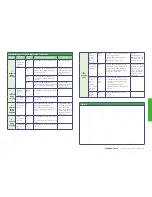
Fault messages
Fault Code
Description
Corrective Action
Brake resistor
overload
The drive software has determined that the brake resistor is
overloaded (based on the values entered in
P
3-13 and
P
3-14),
and trips to protect the resistor. Always ensure the brake resistor is
being operated within its designed parameter before making any
parameter or system changes.
To reduce the load on the resistor, increase deceleration the time,
reduce the load inertia or add further brake resistors in parallel,
observing the minimum resistance value for the drive in use.
Instantaneous over
current on drive
output. Excess load
on the motor.
Fault Occurs on Drive Enable
Check the motor and motor connection cable for phase – phase
and phase – earth short circuits.
Check the load mechanically for a jam, blockage or stalled
condition
Ensure the motor nameplate parameters are correctly entered,
P
1-07,
P
1-08,
P
1-09.
If operating in Vector mode (
P
4-01 – 0 or 1), also check the
motor power factor in
P
4-05 and ensure an autotune has been
successfully completed for the connected motor.
Reduced the Boost voltage setting in
P
1-11
Increase the ramp up time in
P
1-03
If the connected motor has a holding brake, ensure the brake is
correctly connected and controlled, and is releasing correctly
Fault Occurs When Running
If operating in Vector mode (
P
4-01 – 0 or 1), reduce the speed
loop gain in
P
4-03
.
Drive has tripped
on overload after
delivering >100%
of value in
P
1-08
for a period of time.
Check to see when the decimal points are flashing (drive in
overload) and either increase acceleration rate or reduce the load.
Ensure the motor nameplate parameters are correctly entered in
P
1-07,
P
1-08, and
P
1-09
If operating in Vector mode (
P
4-01 – 0 or 1), also check the
motor power factor in
P
4-05 and ensure an autotune has been
successfully completed for the connected motor.
Check the load mechanically to ensure it is free, and that no jams,
blockages or other mechanical faults exist
Over voltage on
DC bus
The value of the DC Bus Voltage can be displayed in
P
0-20
This fault is generally caused by excessive regenerative energy
being transferred from the load back to the drive during braking.
Increase the deceleration ramp time
P
1-04. Check a suitable
brake resistor is connected to the drive.
If operating in Vector Mode, reduce the speed loop gain
P
4-03
Under voltage on
DC bus
This occurs routinely when power is switched off.
If it occurs during running, check the incoming supply voltage, and
all connections into the drive, fuses, contactors etc.
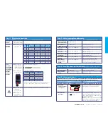
Useful parameters
Parameter
Function
P1-01
Maximum Frequency
P2-24
Output PWM switching frequency
P3-06
Output contactor closing time
P3-07
Brake release time
P3-08
Brake Apply delay
P3-09
Brake Apply speed
P3-10
Zero speed holding time on disable
P4-01
Motor control mode (0=Advanced vector, 1=Basic vector, 2=V/F mode)
P4-03
Speed loop P-gain
P4-04
Speed loop I-gain
External trip
E-trip requested on control input terminals. Some settings of
P
1-13 require a normally closed contactor to provide an external
means of tripping the drive in the event that an external device
develops a fault. If a motor thermistor is connected check if the
motor is too hot.
Input phase loss trip
Drive intended for use with a 3 phase supply, one input phase has
been disconnected or lost.
Drive output fault
Drive output fault. Check correct control terminal connections.
Check for output contactor faults.
Internal STO circuit
Error
Check supply to terminal T12 is >18V, otherwise Refer to your
Invertek Sales Partner
Encoder Feedback
Faults (Only visible
when an encoder
module is fitted and
enabled)
Encoder communication /data loss
Encoder Speed Error. The % error between the measured encoder
feedback speed and the drive estimated rotor speed is greater than
the value set in
P
6-07.
Incorrect Encoder PPR count set in parameters
Encoder Channel A Fault
Encoder Channel B Fault
Encoder Channels A & B Fault
Output (Motor)
Phase Loss
One of the motor output phases is not connected to the drive,
check motor is connected.


