
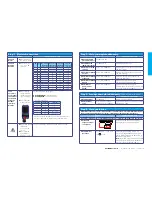


Control terminal connections
(default)
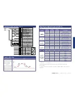
Digital input configuration parameter (P1-13)
The below table assumes the drive already has a direction command given i.e. Terminal 2 or 3 input
is high
P1-13
Digital
Input 3 (T4)
Analog
Input 1 (T6)
Analog
Input 2 (T10)
Active Speed
1
(Option 1)
Default
1
0
0
P
2-02 (HighSpeed)
0 or 1
0
1
P
2-03 (Intermediate Speed)
0 or 1
1
0 or 1
P
2-04 (Inspection Speed)
0
0
0
P
2-01 (Levelling Speed)
2
(Option 2)
1
0
*1
P
2-02 (High Speed)
0 or 1
1
*1
P
2-04 (Inspection Speed)
0
0
*1
P
2-01 (Levelling Speed)
3
(Option 3)
1
0
0
P
2-02 (High Speed)
0 or 1
1
0
P
2-04 (Inspection Speed)
0
0
0
P
2-01 (Levelling Speed)
4
(Option 4)
1
0
**1
P
2-02 (High Speed)
0 or 1
1
**1
P
2-04 (Inspection Speed)
0
0
**1
P
2-01 (Levelling Speed)
5 (Option 5)
Brake release monitoring function see ‘Optidrive P2 Elevator User Guide’
6
(Option 6)
(Multispeed
Selection)
0
0
0
P
2-01
1
0
0
P
2-02
0
1
0
P
2-03
1
1
0
P
2-04
0
0
1
P
2-05 (Max 5.0Hz)
1
0
1
P
2-06
0
1
1
P
2-07
1
1
1
P
2-08
1= Input High
0 = Input Low
* If 0 the drive will trip on External trip or F-Ptc if a motor thermistor fitted and Ptc-th has been
selected in
P
2-33.
** If 0 drive will fast stop using deceleration ramp in time set in
P
2-25., if
P
2-25 is zero the drive will
coast to stop.
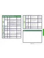
Speed profile setup
Related Parameters
Action
P
1-03 (Accel ramp time)
P
1-04 (Decel ramp time)
P
2-01 (Levelling Speed)
P
2-02 (Run Speed)
P
2-03 (Intermediate
Speed)
P
2-04 (Inspection Speed)
P
3-01 (Accel start Jerk)
P
3-02 (Accel end Jerk)
P
3-03 (decel start Jerk)
P
3-04 (decel end Jerk)
P
3-05 (Stopping Jerk)
+24Vdc 100mA Output
+10Vdc 10mA Output
Open = Terminal 4 Selection
Closed = Inspection Speed
0V
Drive Healthy (24Vdc Output)
0V
Open = Terminal 4 Selected Speed
Closed = Intermediate speed
Drive Running (24Vdc Output)
ST0 +
ST0 -
RL1-C
RL1-NO
RL1-NC
RL2-A
RL2-B
1
2
3
4
5
6
7
8
9
10
11
12
13
14
15
16
17
18
+24Vdc
0Vdc
Optional
External
Power
Supply
Open = Levelling Speed
Closed = High Speed
Motor Contactor
Control
Common
Motor Brake
Control
Common
Open = StoP
Closed = Run Up (Forward)
Open = StoP
Closed = Run Down (Reverse)
OPTIDRIVE elevator
| Quick Start-up Guide | Version 1.0


