Technical specifications
INTORQ | BA 14.0200 | 02/2016
13
Double-rotor design
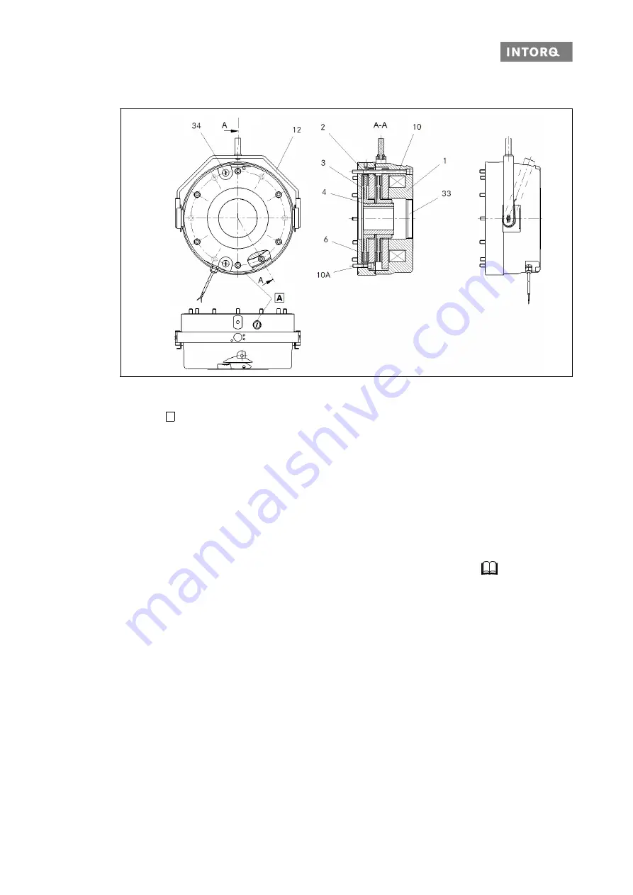
Fig. 2
Design of the BFK471-25 spring-applied brake, double-rotor design
The spring-applied brake is designed for converting mechanical work and kinetic energy into heat energy.
Due to the static braking torque, loads can be held at standstill. Emergency braking is possible at high speed
of rotation. The wear increases as the switching energy increases (operating speeds
15).
The spring-applied brake is a disc brake with two or four friction surfaces, depending on the design. The brak-
ing torque is generated by several pressure springs with friction locking. The braking circuits are released
electromagnetically.
3.1.2
Brakes
During the braking procedure, the pressure springs use the armature plate (2) to press the rotor (3) (which
can be shifted axially on the hub (4)) against the friction surface. The asbestos-free friction linings ensure
high braking torque and low wear. The braking torque is transmitted between the hub (4) and the rotor (3)
via gear teeth.
A
A
Check hole, air gap with plug screw
1
Stator, complete
4
Hub
12 Manual release
2
Armature plate
6
Flange
33 Hollow shaft end cover
3
Complete rotor
10 Six socket head cap screws, DIN EN ISO 4762
34 Plug screw
10A Six socket head cap screws, DIN EN ISO 4762
(short)


