www.intertec.info
Operating Instructions SL MINITHERM DNLA
Page 4 / 8
HOM177850763Ien-7
INTERTEC-Hess GmbH · Raffineriestr. 8 · 93333 Neustadt/Donau · Germany ·
+49 9445 9532-0 · [email protected]
5
Installation accessories
The following are included in the scope of delivery:
Piece
Description
1
Heating unit
1
Angle bracket made of flat steel
1
Packet of screws containing the following:
2
M 6x12 hexagon bolts
1
T-head bolt type 28/15, M 6x15
1
Washer shape A 6.4
2
Lock washers shape J 6.4
If one of the components listed here is not included in
the scope of delivery, then please contact the
manufacturer.
6
Technical Data
Protection class
IP66/IP68 1bar/30min
Rated voltage
max. 265 V AC
Permitted operating voltage
max. 275 V AC
Rated current (in
compliance with VDE 0298)
max. 10 A
Ambient temperature
- 60 to + 60°C
Max. permitted operating
temperature
- 60 to + 180°C
Switching capacity of fault
alarm (AM)
10 A / 275 V AC
Connecting cable
Silicone hose cable,
notch- and oil resistant, 3
x 1,5 mm²
Connecting cable AM
Silicone hose cable,
notch- and oil resistant, 5
x 1,0 mm² Ø8,5 mm
Material
Seawater-proof
aluminium, black
anodized
Mean Time Before Failure
50.000 h
Storage temperature
- 60 to + 80°C
Profile type "L" Length x
Width x Height
109 x 211 x 40
mm
Profile type "L SF" Length x
Width x Height
109 x 127 x 40
mm
INFO
You will find the precise technical data for your
instrument on the label. You will find information on
the heating output on the data sheet.
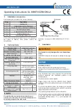
Rated output
Rated voltage/Operating voltage
Thermostat
Illustration 1:
Example: SL MINITHERM DNLA 70 70 TS10
label
7
Installation
WARNING
The heater is only designed for non hazardous
areas.
INTERTEC-Hess GmbH accepts no liability for improper
use.
NOTICE
Carefully remove
When removing from the packaging and during
transport, the connection line must not be stressed or
bent.
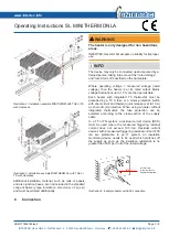
Free convection may not be impeded. You will find the
minimum distances and installation position in the
following figure.
The label needs to remain legible.
Please make sure that the absolute heat transfer
coefficient of the surrounding housing is not smaller than
0.5 W/K.
To ensure operational safety, the heater must operate
under temperature conditions which will NOT exceed the
trigger temperature of the limiter.
The operating temperatures must be adhered to.
The connection cable must be permanently installed up
to the inlet into the on-site junction box, taking the
permissible bending radius = 5 x outer diameter into
consideration.


