background image


2  

Simon XT/XTi GSM Module V4 Installation Instructions 

Installation 

Installation consists of inserting the module into the panel, 

attaching the antenna, and performing a GSM phone test at 

the panel.   

Follow these guidelines during installation: 

• 

Before affixing the panel to a wall, verify the HSPA signal 

level at the installation location.  On the XT panel, press 

and hold the 5 key for 10 seconds to view the HSPA signal 

level

.  On the XTi panel, enter ‘Programming’ 


‘Interactive Services’ 


‘Modules Status’.  With either 

panel, module LED L4 blinks to indicate signal strength. 

(See Tables 1-3 for LED details.)  An installation location 

with a sustained signal level of two or more bars is 

recommended.  

• 

Do not exceed the panel total output power when using 

panel power for the HSPA module, hardwired sensors, 

and /or sirens. Refer to the specific panel installation 

instructions for details. 

• 

Only one Alarm.com HSPA module can be used per 

Simon XT or XTi panel. 

• 

The HSPA module draws a maximum of 30 mA average 

during normal operation. In PowerSave mode, during or 

immediately following an AC power failure, the module will 

draw only 10 mA on average. 

• 

Avoid mounting the panel in areas with excessive metal or 

electrical wiring, such as furnace or utility rooms. 

• 

Leave 12 to 18 in. of open space around the module 

antenna. 

• 

Do not install the control panel and module in a basement 

or other below-ground location. Doing so will negatively 

impact HSPA signal strength. 

Tools and supplies needed 

You will need the following tools and supplies: 

• 

Small flat-head and Phillips screwdrivers 

• 

Screws (included) 

• 

Antenna (included)


Module insertion and antenna installation 

Before installing the module, disconnect the battery and AC 

power from the panel.  

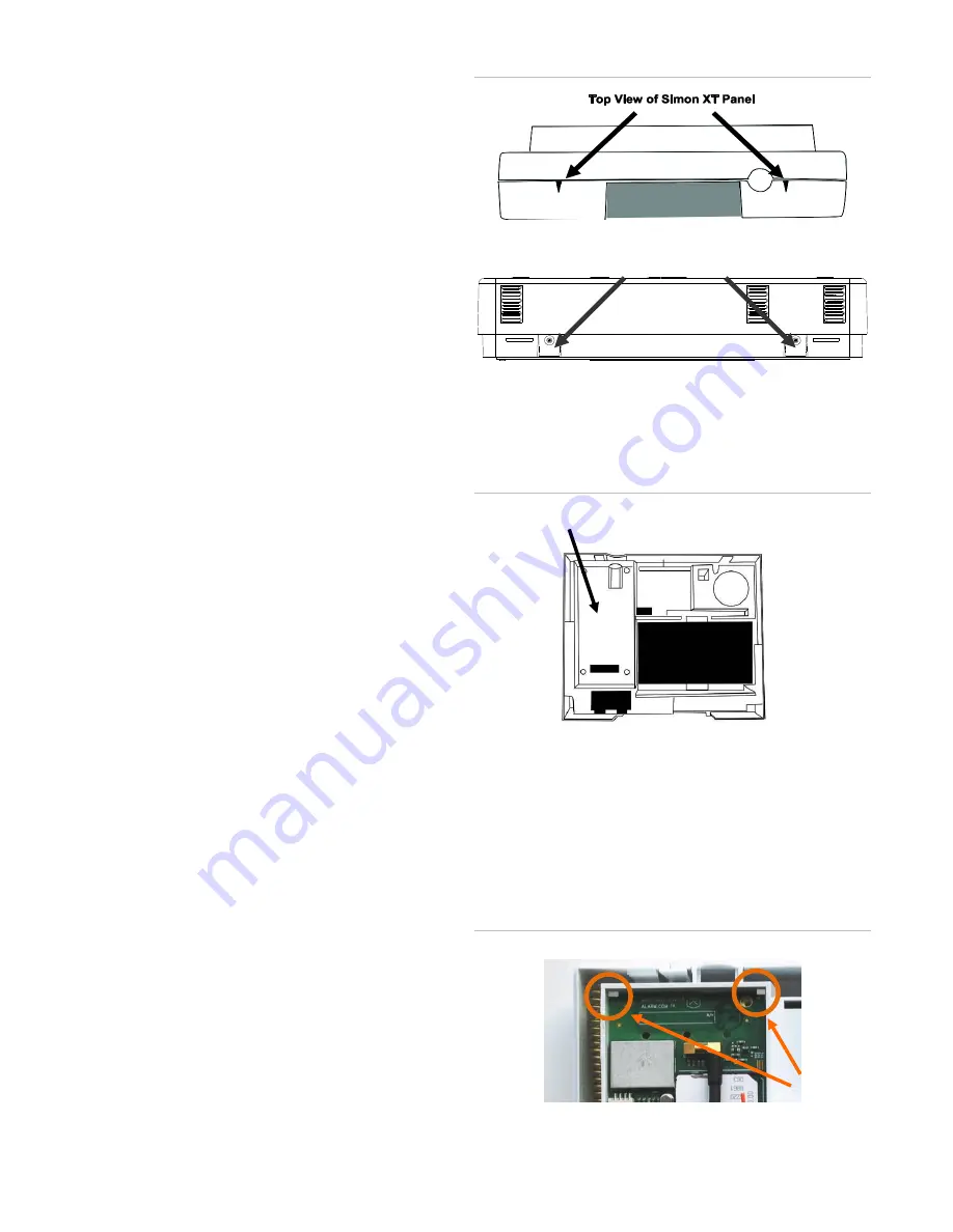
1.  Open the panel by pressing the two tabs (Figure 1 below) 

on the top of the XT or by lifting tabs on the XTi panel.  

Figure 1: Top view Simon XT and XTi panels 


2.  The module compartment can be found behind the front 

panel that swings down, to the left of the battery 

compartment as seen in Figure 2 below  

Figure 2: Module compartment 


3.  Push antenna end into module connector to snap the 

antenna onto the module.  The module must be seated 

correctly beneath the two small, plastic corner tabs (see 

Figure 3 below) to ensure it fits into the compartment 

properly. 

Figure 3: Module plastic corner tabs 

Top of panel 


Top View of Simon XTi Panel 

Plastic 
Corner  

Tabs


Module Compartment


Bottom of Panel, near hinge 

Summary of Contents for Simon XTi

Page 1: ...e used as the primary communication path for all alarm signaling or as a backup to a telephone line connection to the central monitoring station The wireless alarm signaling and routing service is operated by Alarm com The V4 module also features integrated support for Alarm com s emPower TM solution with built in Z Wave capabilities The module interfaces with the Simon XT and XTi panel boards fit...

Page 2: ...aw only 10 mA on average Avoid mounting the panel in areas with excessive metal or electrical wiring such as furnace or utility rooms Leave 12 to 18 in of open space around the module antenna Do not install the control panel and module in a basement or other below ground location Doing so will negatively impact HSPA signal strength Tools and supplies needed You will need the following tools and su...

Page 3: ...1 2 The panel will display GSM Comm Test in progress to indicate the test has been initiated To perform the phone on a Simon XTi 1 Press the Status Settings icon on the lower right of the home screen 2 Scroll Down and press Programming 3 Enter the installer code default 4 3 2 1 then OK 4 Press System Tests 5 Press Comm Test The panel will display GSM Comm Test in progress to indicate the test has ...

Page 4: ...le firmware version e g 4152a 3 Key 15 digit SIM card number 5 Key Wireless signal strength level and module status or error if any The panel will display bars for the signal level 0 to 5 and a number 2 to 31 followed by the Mode it is in See GSM Module Statuses on Table 1 6 Key Battery voltage as read by the module to two decimal places and the AC power status e g Battery 6 79v AC Power OK 8 Key ...

Page 5: ...arious possibilities Table 5 Z Wave LED status indicators LED 2 LED 5 Device status or error Description 4 blink Add mode lasts 120 seconds or until a device is added In this mode you can add a device to the local Z Wave network Devices cannot be added to a network if they are already a part of a network 2 blink Delete mode lasts 120 seconds or until a device is deleted In this mode you can delete...

Page 6: ...imal wireless signal strength Install the module above ground level as high up as possible within the structure Install the module near or adjacent to an outside facing wall of the structure Do not install the module inside a metal structure or close to large metal objects or ducts Make sure to follow the antenna positioning guidelines that are included with the antenna Certain antennas must be or...

Page 7: ... Interactive Services Scroll up to Interactive Services and press OK Sensor Reporting Test This menu is used to automate the process of confirming that all sensors report correctly to the Central Station It will put the account on test and request the list of sensors that did not report correctly It is available only to installers who have integrated their sensor testing process with the Central S...

Page 8: ...en activated or request an Installer Peek In Now to test image capture Delete1 Delete Image Sensors from the panel Set Dealer Logo Send the dealer logo to the panel and touch screen Only available for dealers who have set up this feature with Alarm com Weather Update Request a Weather Update if the weather forecast is not showing on the XTi touch screen To speed up the process stay in Programming ...

Page 9: ...o a different Z Wave network before you can learn it into the GSM module Update 2WTTS Press Update 2WTTS to force an update of the thermostat lights or locks information shown on the touch screen 2WTTS Note that these updates may take several minutes to complete Thermostats View thermostat data and update remove thermostats from display on the panel and touch screens Lights Update the lights list ...

Page 10: ...o an outlet on a circuit different from that which the receiver is connected Consult the dealer or an experienced radio TV technician for help This equipment complies with the FCC RF radiation exposure limits set forth for an uncontrolled environment This equipment should be installed and operated with a minimum distance of 20 centimeters between the radiator and your body Under Industry Canada re...

Reviews: