background image

2 / 7 


 P/N 466-5438 • REV A • ISS 16OCT18 

Preparation

To begin 

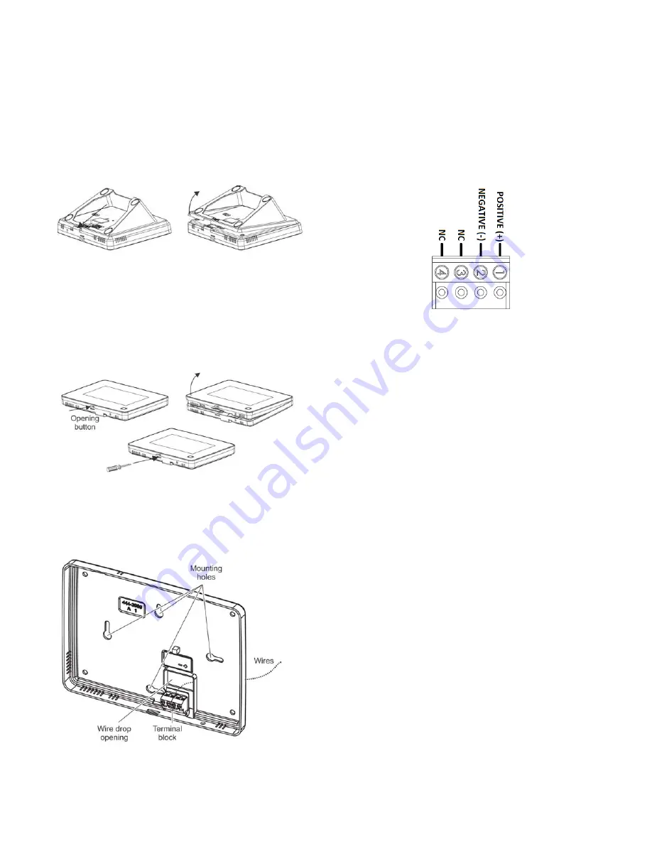
1.  Separate the touch screen and the mounting base from 

the preassembled desktop stand. Remove the desktop 
stand by holding the touch screen unit with one hand and 
prying the desktop stand at the removal tab marking until it 
separates (Figure 1) with the other. Put the desktop stand 
aside temporarily. 

Figure 1:  Desktop stand removal 

2.  Remove the touch screen from the mounting base 

pressing the opening button on the bottom of the touch 
screen (as shown in Figure 2). In case the parts stick to 
each other, try to separate them by inserting a small 
screwdriver into the opening slot beneath the protruding 
opening button (Figure 2). 

Figure 2:  Opening slot

3.  Feed the supplied power wire through the backside of the 

wire drop in the mounting base (Figure 3). 

Figure 3:  Power Wire Routing in the Mounting 

Base

4.  Connect the wire to the power terminals as identified in 

Figure 4, taking particular care to ensure the 
marked/dashed wire attaches to the Positive lead and the 
unmarked wire attaches to the Negative lead. Observe 
polarity by ensuring the same wire at the touch screen 
mounting base is connected to the corresponding positive 
and negative lead on the power supply. Do not use 
different or longer run cable than the supplied wiring as 
the DC power supply may not support it and intermittent 
power failures in the touch screen may occur due. 

Figure 4:  Power connector

5.  Reattach the touchscreen to the mounting base plate. 

Angle the top of the touch screen into the tab hooks on the 
top of the mounting base and swing the bottom of the 
touch screen into the lower part of the mounting base until 
you hear an audible click. 

6.  Connect the spaded ends of the power supply wire to the 

terminal to the terminals on the power supply.  

Note: 

The dashed line/writing side of the wire to positive. 
Ensure consistency by wiring the + to + and – to – as 
polarity must be observed or touchscreen will not 
function. Plug in the power, the touch screen will power 
up.

Learning

To program (learn) the touch screen into the Simon XT 
panel: 

1.  Press the down arrow button on the panel and scroll to 

System Programming. 

2. Press 

OK. 


The panel displays 

Enter Code

.

3.  Enter the installer access code and press OK. 

4.  Scroll to Sensors and press OK. 

5.  When the panel displays

 Learn Sensor,

 press OK. 

The panel blinks

Trip Sensor nn 

(where nn is the next 

available zone number). You can enter a different zone 
number if desired. 

Summary of Contents for 60-924-RF-TS5-2

Page 1: ...el x Customize color and fonts matching the interactive service on the mobile phone Xti 5 Panel Version 2 only Safety Information IMPORTANT SAFETY INFORMATION READ ENCLOSED WARNINGS AND SAFETY INFORMATION WARNING CHOKING HAZARD The product accessory bag contains items that could be choking hazards Please keep away from small children WARNING Disconnect panel power before servicing CAUTION Use stat...

Page 2: ...ch screen mounting base is connected to the corresponding positive and negative lead on the power supply Do not use different or longer run cable than the supplied wiring as the DC power supply may not support it and intermittent power failures in the touch screen may occur due Figure 4 Power connector 5 Reattach the touchscreen to the mounting base plate Angle the top of the touch screen into the...

Page 3: ...ouch screen should indicate it is waiting for enrollment 6 On the panel you can now program the group number 00 01 04 05 06 or 07 by pressing EDIT next to Sensor Group 7 On the panel select a name for the touch screen by pressing EDIT next to Sensor Name You can select something simple such as Touch Pad or use additional descriptors such as Bedroom Touch Pad The touch screen will indicate enrollme...

Page 4: ...you cannot get the touch screen to trip test a known good touch screen at the same location If the replacement touch screen functions contact UTC Fire Security for repair or replacement of the faulty touch screen Mounting 1 With touch screen operation verified and tested at the permanent location mount the touchscreen either on the wall or on a surface with the supplied desktop stand Surface deskt...

Page 5: ...ed to be checked by a qualified technical at least every 3 years Setting the clock You can set the touch screen clock by setting the clock on the Simon XT XTi XTi 5 or XTi 5 V2 panels Battery Pack Replacement We recommend that you replace the backup battery pack every 3 5 years Only the part 60 924 BAT4SIMONTS5 can be used as a battery pack replacement 1 Remove the touch screen from the mounting p...

Page 6: ...lled by the following sensors All sensors learned into Group 43 Sensors that are not named window or door Sensors not learned into the Motion groups Sensors that are named keyfob or keychain Specifications Compatibility Simon XT version 1 3 and later Simon XTi Simon XTi 5 Enhanced Compatibility XTi 5 Version 2 i e 80 zone encryption GUI Power Input 100 120 VAC 250 mA Output 6 VDC 1000 mA Backup ba...

Page 7: ...ser un mauvais fonctionnement du dispositif Conforms to UL 985 Household Fire Warning System Units UL 1023 Household Burglar Alarm System Units ULC C1023 Preliminary Standard for Household Burglar Alarm ULC S545 Standard For Residential Fire Warning System Control Units Warnings and Disclaimers THESE PRODUCTS ARE INTENDED FOR SALE TO AND INSTALLATION BY QUALIFIED PROFESSIONALS UTC FIRE SECURITY CA...

Reviews: