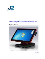
J2 225, System Manual
Get the most out of your LG 225 with our comprehensive (Spanish) Guía Del Usuario. This essential manual covers every feature, ensuring seamless operation. Download it for free from manualshive.com and enjoy hassle-free navigation of your device. Unlock its full potential with our convenient, downloadable manual.
Share
Download


Reviews:
No comments
Related manuals for 225
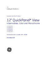
QuickPanel+ IC754VSI12CTD
Brand: GE Pages: 96
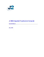
580
Brand: J2 Pages: 38
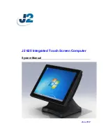
625
Brand: J2 Pages: 52
VERSA IC
Brand: IBC Pages: 10
HS2TCHP
Brand: NEO Pages: 36
Frame
Brand: TablerTV Pages: 4
uEZ GUI
Brand: FDI Pages: 30
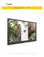
EntryLine UHD series
Brand: Prowise Pages: 54

Lightcloud Touch
Brand: RAB Lighting Pages: 10
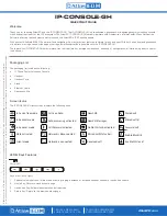
IP-CONSOLE-GH
Brand: Atlas IED Pages: 8
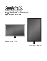
DS-4217TSL
Brand: SunBriteDS Pages: 4
DTH-1320
Brand: Wacom Pages: 11
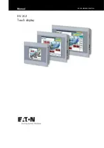
XV100
Brand: Eaton Pages: 80
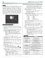
Equinox 73-II
Brand: Vantage Hearth Pages: 4
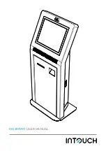
KIO190VRT
Brand: InTouch Pages: 4
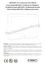
DSC HS2TCHP
Brand: Tyco Pages: 132
CINTIQ DTK-2700
Brand: Wacom Pages: 27

elo TOUCHSYSTEMS E Series
Brand: TE Connectivity Pages: 2


