


PCI-4302
Interface Corporation
-32-
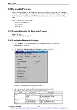
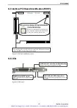
6.5 Interface Product Pin Assignments
ATN
SRQ
IFC
NDAC
NRFD
DAV
EOI
DIO4
DIO3
DIO2
LOGIC GND
GND
GND
GND
GND
GND
GND
REN
DIO8
DIO7
DIO6
DIO5
1
12
10
9
8
6
5
4
3
2
13
23
24
22
21
20
19
18
17
16
15
14
7
11
SHIELD
DIO1
Figure 6.3 I/O connector pin assignment
6.6 Signals
Signal Description
Signal
Pin Number
Direction
Description
DIO1 through /DIO4
1 through 4
DIO5 through /DIO8
13 through 16
Transmits data. (command, address, and so on)
EOI
5
Marks the end of a data message/executes a parallel
poll. (End or Identity)
DAV
6
Indicates data is enabled. (Data Valid)
NRFD
7
Indicates the device is ready or not ready to receive
data. (Not Ready For Data)
NDAC
8
Indicates the device accepts/does not accept data.
(Not Data Accepted)
IFC
9
Initializes an interface. (Interface Clear)
SRQ
10
Requests a service. (Service request)
ATN
11
Input/Output
Classifies data. (Attention)
SHIELD
12
-
Indicates signal ground.
REN
17
Input/Output
Indicates the switching of a device remort/rocal
control (Remort Enable)
GND
18 through 23
-
Indicates ground.
LOGIC GND
24
-
Indicates logic ground.
Artisan Technology Group - Quality Instrumentation ... Guaranteed | (888) 88-SOURCE | www.artisantg.com


