


PCI-4302
-25-
Interface Corporation
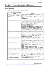
Chapter 5 Troubleshooting and Diagnosis
5.1 Checkpoints
If the
PCI-4302
doesn’t work correctly, check the following points.
Table 5.1 Checkpoints for Troubleshooting
Problem
Solution
<Windows XP, Windows 2000, Windows Me, Windows 98, and
Windows 95>
Enable the Plug and Play capability in the BIOS setup program on the
computer.
The device manager shows an exclamation
point or X beside
Interface PCI GPIB
in
the device tree.
<Windows NT 4.0>
Disable the Plug and Play capability in the BIOS setup program on the
computer.
Double-check all cable connections.
If the power requirements exceeds the system power budget, the circuits on
the board or connected external circuits cannot be powered properly.
Prepare an external power supply for your PCI board.
Remove and re-install the device driver correctly.
See “Chapter 3 Installation,” page 13.
The board does not operate correctly.
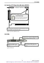
The device driver checks the RSW1 value of each board for identification
purposes. If the RSW1 value of one board conflicts with that on another
identical board in the same system, then the device driver may not work.
When two or more identical boards are installed in a single system, each
RSW1 must be set to a unique value. See “6.3 Interface PCI Board
Identification (RSW1),” page 31.
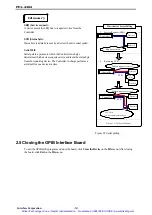
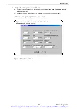
Register the board by using the control panel applet
Interface GPIB
Board System Configuration
in the
Control Panel
.
See “3.8 Configuring the Driver Software Parameters,” page 18.
Driver software does not work as expected.
Specify the same number as on the RSW1 value on the board in
Board
number
in the control panel applet
Interface GPIB Board System
Configuration
in the
Control Panel
.
See “3.8 Configuring the Driver Software Parameters,” page 18.
Register the board by using the control panel applet
Interface GPIB
Board System Configuration
in the
Control Panel
.
See “3.8 Configuring the Driver Software Parameters,” page 18.
When running a sample program, an error
message is displayed.
<Windows XP, Windows 2000,
Windows NT 4.0>
A System Administrator should install the driver correctly.
Configure the termination method of the board properly corresponding to
that of the devices on the bus.
Make sure that the target device is correctly addressed as a Talker or a
Listener.
Make sure that there are no conflicting GPIB address.
Errors occur during data transfer.
Configure the time-out value enough long to enable devices to respond the
request of the transfer.
The control for indefinite period at data
transfer does not respond. It seems to be
hung.
Make sure that GPIB addresses of the devices on the bus are configured
properly and your program correctly addresses the devices. In this case,
your program is waiting for a completion of the data transfer. After the
transfer has been successfully completed or time-out has occurred, your
application returns the control.
An error code of -7 is returned when
sending the Device Clear message.
Configure the time-out value for GPIB bus commands longer by using the
control panel applet
Interface GPIB Board System Configuration
in the
Control Panel
.
See “3.8 Configuring the Driver Software Parameters,” page 18.
The computer does not respond after
Standby mode. (Input and output are
disabled.)
Set the System standby setting to “Never”.
Artisan Technology Group - Quality Instrumentation ... Guaranteed | (888) 88-SOURCE | www.artisantg.com


