background image

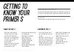
i n c l u d e d   t o o l   k i t

1.  PH1 Philips driver
2.  PH2 Philips driver
3.  Long reach 5 mm HEX/Allen driver
4.  Torque wrench extension
5.  2 mm HEX/Allen driver
6.  2.5 mm HEX/Allen driver
7.  3 mm HEX/Allen driver
8.  4 mm HEX/Allen driver
9.  Flat head driver
10. 5 mm HEX/Allen driver
11.  6 mm HEX/Allen driver
12. 8 mm HEX/Allen driver

13. T25 Torx driver
14.  T30 Torx driver
15. T40 Torx driver
16.  1/4" drive-to-1/4" drive bit adaptor
17.  1/4" drive-to-3/8" drive adaptor
18. Torque Wrench
19.  3-way Y-wrench Multi-HEX/

Allen tool (4 mm, 5 mm, 6 mm)

20. T25 Torx tool
21.  INTENSE Shock Pump
22.  Maxima grease
23.  Tire plasma

1 8


// 

2 0 2 1   p r i m e r   u s e r   m a n u a l

assembly

Preface // 

Service and maintenance on an INTENSE cycle requires special tools, 
abilities and knowledge of bicycle mechanics. Although each INTENSE 
bicycle is supplied with a tool kit, it is recommended to use an authorized 
INTENSE dealer for service and maintenance. Failure to follow these 
instructions may result in serious bodily injury or death. 

P r o   t i p s

•  Use grease on any metal to carbon interface, including headset. Also 

use grease on metal to metal interface of threaded BB.

•  After the first few rides and all the components are broken in and settled 

into place, go through and re-torque all pivot axles and fasteners. After 
this first adjustment, you will be ready to rip for the long haul.

1

5 6 7 8 9 10 11 12 13 14 15

16 17

18

19

20

2

3

4

21

22

23

Summary of Contents for PRIMER 275

Page 1: ...primer s primer 29 user manual primer 275...

Page 2: ...hing more than to throw a leg over a sweet bike and head out for a rip We re so glad you ve joined us Welcome to INTENSE enjoy your experience the primer family Designed for the trail enthusiast the P...

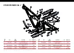
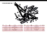
Page 3: ...8 Geometry 9 Exploded View and B O M 10 Getting to Know Your Primer 275 12 Frame Features Component Spec 12 Geometry 13 Exploded View and B O M 14 Assembly 18 Frame Assembly 19 Torque Specifications 2...

Page 4: ...Component Spec Fork Ohlins 150 mm with 51 mm Fork Offset 570 mm axle to crown Rear Shock 210 x 50 20 mm x 8 mm rear reducer and 20 mm x 6 mm for front triangle mount Headset Cane Creek 40 alloy cartr...

Page 5: ...0 mm 3 5 100 mm 3 9 100 mm 3 9 120 mm 4 7 120 mm 4 7 E Headtube Angle 65 3 64 7 65 3 64 7 65 3 64 7 65 3 64 7 F Reach 407 mm 16 401 mm 15 8 437 mm 17 2 431 mm 17 462 mm 18 2 456 mm 18 492 mm 19 4 486...

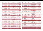
Page 6: ...X 12 mm Boost 1 11 Nm 100 in lbs 2 Bearing Spacer 130758 Lower Link Bearing Spacer Rear 1 N A 3 Bearing Cap 130765 Upper Link Bearing Cap 24 mm Upper 2 N A ITEM NO ITEM PART NUMBER DESCRIPTION QTY TOR...

Page 7: ...Clamp 1 N A 25 Zerk Fitting 401011 M6 x 1 0 1 5 Nm 45 in lbs ITEM NO ITEM PART NUMBER DESCRIPTION QTY TORQUE SPEC 26 BHCS M5 x 12 410010 Water Bottle Bolt Button Head M5 x 12 2 2 Nm 18 In Lbs 27 SHCS...

Page 8: ...earings and dedicated frame hardware Component Spec Fork FOX 34 150 mm with 51 mm fork offset 561 mm axle to crown Rear Shock 210 x 50 20 mm x 8 mm rear reducer and 20 mm x 6 mm front reducer Headset...

Page 9: ...mm 3 5 90 mm 3 5 100 mm 3 9 100 mm 3 9 120 mm 4 7 120 mm 4 7 E Headtube Angle 65 7 65 1 65 7 65 1 65 7 65 1 65 7 65 1 F Reach 411 mm 16 2 405 mm 16 442 mm 17 4 435 mm 17 467 mm 18 4 461 mm 18 497 mm 1...

Page 10: ...ER DESCRIPTION QTY TORQUE SPEC 1 Rear Axle 130757 Axle Rear 148 mm x 12 mm Boost 1 11 Nm 100 in lbs 2 Bearing Spacer 130758 Lower Link Bearing Spacer Rear 1 N A 3 Bearing Cap 130765 Upper Link Bearing...

Page 11: ...Bolt On Seat Clamp 1 N A 25 Zerk Fitting 401011 M6 x 1 0 1 5 Nm 40 in lbs ITEM NO ITEM PART NUMBER DESCRIPTION QTY TORQUE SPEC 26 BHCS M5 x 12 410010 Water Bottle Bolt Button Head M5 x 12 2 2 Nm 18 i...

Page 12: ...omponent Spec Fork FOX 34 150 mm with 44 mm fork offset 543 6 mm axle to crown Rear Shock 210 x 50 20 mm x 8 mm rear reducer and 20 mm x 6 mm for front triangle mount Headset Cane Creek 40 Alloy Cartr...

Page 13: ...13 105 mm 4 13 115 mm 4 5 115 mm 4 5 130 mm 5 1 130 mm 5 1 E Headtube Angle 65 64 4 65 64 4 65 64 4 65 64 4 F Reach 410 mm 16 1 404 mm 15 9 434 mm 17 1 428 mm 16 9 457 mm 18 453 mm 17 8 491 mm 19 3 4...

Page 14: ...30757 Axle Rear 148 mm x 12 mm Boost 1 11 Nm 100 in lbs 2 Bearing Spacer 130758 Lower Link Bearing Spacer Rear 1 N A 3 Bearing Cap 130765 Upper Link Bearing Cap 24 mm Upper 2 N A ITEM NO ITEM PART NUM...

Page 15: ...1 N A 25 Zerk Fitting 401011 M6 x 1 0 1 5 Nm 45 in lbs ITEM NO ITEM PART NUMBER DESCRIPTION QTY TORQUE SPEC 26 BHCS M5 x 12 410010 Water Bottle Bolt Button Head M5 x 12 2 2 Nm 18 in lbs 27 SHCS M6 x...

Page 16: ...1 6 2 0 2 1 p r i m e r u s e r m a n u a l...

Page 17: ...I N T E N SE 1 7...

Page 18: ...0 2 1 p r i m e r u s e r m a n u a l assembly Preface Service and maintenance on an INTENSE cycle requires special tools abilities and knowledge of bicycle mechanics Although each INTENSE bicycle is...

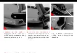
Page 19: ...toptube pivot point making sure that spacers do not fall out Image 2 C Using top link collet bolt 130842 insert into non drive side of frame and push through the top link then thread into the frame ta...

Page 20: ...the two pivot axle spacers 130860 to hold spacers against the inside of the lower link bearing race Image 5 B Match link to front triangle and from non drive side insert greased lower pivot axle 13080...

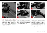
Page 21: ...er link 130858 Image 8 B Mate rear triangle with lower link and align pivot points with bearing caps Image 9 C With lower pivot points aligned insert main pivot bolt 130791 using an 8 mm HEX Allen wre...

Page 22: ...aps 130835 This will help hold the bearing caps in place during the installation Align the swing arm pivot with upper link pivot point and bearing cap Image 12 B Insert non drive D lock reducer Flip C...

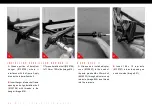
Page 23: ...Image 15 B Align rear of shock to D Lock reducers and link spacers on the top link insert shock shoulder bolt left into the D Lock reducer on the non drive side Image 16 16A C Confirm the D Lock shoul...

Page 24: ...ert 148 x 12 rear axle 130757 into axle opening on non drive side Image 21 21 20 I N S T A L L I N G D E R A I L L E U R H A N G E R A Grease portion of derailleur hanger 130790 where it interfaces wi...

Page 25: ...hten the axle Torque to 11 Nm or 100 in lbs Image 22 D On the non drive side use a 5 mm HEX Allen wrench and torque the cone adjuster to 14Nm or 125 in lbs Image 23 S E A T C L A M P A Install seat cl...

Page 26: ...llen 11 Nm 100 in lbs Axle drive side 5 mm HEX Allen 11 Nm 100 in lbs M6 x 22 Bolt non drive side 5 mm HEX Allen 14 Nm 125 in lbs torque specifications Achieving proper torque is vital to ensuring the...

Page 27: ...s Over tightening the seatpost clamp will inhibit the movement of the seatpost and potentially damage seatpost and or seat tube setup Preface We are almost ready to rip Just a few more checkpoints and...

Page 28: ...the o rings have been set P r o T i p Here is where having a friend helps Have them straddle the front wheel and pull the handlebars in a upward direction as to not allow the suspension to compress a...

Page 29: ...hen sitting on the bike Shock Ohlins TTX22M Shock 210 x 50 mm 20 x 6 mm Front 20 x 8 mm Rear Reducer RIDER WEIGHT LBS KGS spring weight lbs High Speed Compression 3 Levels Low Speed Compression 16 Cli...

Page 30: ...ting on the bike Fork Sag 20 when sitting on the bike Shock Fox Float DPX2 Shock 210 x 50 mm RIDER WEIGHT LBS KGS Air Pressure PSI REBOUND clicks out from fully closed Closed is Clockwise Open is Coun...

Page 31: ...ike Fork Sag 20 when sitting on the bike Shock Fox Float DPX2 Shock 210 x 50 mm RIDER WEIGHT LBS KGS Air Pressure PSI REBOUND clicks out from fully closed Closed is Clockwise Open is Counter Clockwise...

Page 32: ...xactly how the geometry is affected please refer to the geometry chart A d d i t i o n a l N o t e s To get the rear triangle and the flip chip to completely install in the Low setting the rear triang...

Page 33: ...shock bolt 410050 with 4 mm HEX Allen wrench in right hand push down on rear shock and lower the back of the shock out of the way then snug the front shock bolt to hold shock and prevent it from hitti...

Page 34: ...ill decrease the level of performance and possibly cause injury or death Use a soft cloth with warm soapy water to clean the carbon surfaces Do not use high pressure washers abrasive cloths or cleaner...

Page 35: ...re inspect for leaks X Deraileur Cables Inspect and lube X Seatpost Clean and regrease interface with frame X Frame Pivots Remove pivot bolts check bearings for pitting and wear X Headset Disassemble...

Page 36: ...1 C u s t o m e r S e r v i c e t e c h c e n t e r i n t e n s e c y c l e s c o m G e n e r a l I n f o i n f o i n t e n s e c y c l e s c o m I n t e n s e l l c 4 2 3 8 0 r i o n e d o T e m e c...

Reviews: