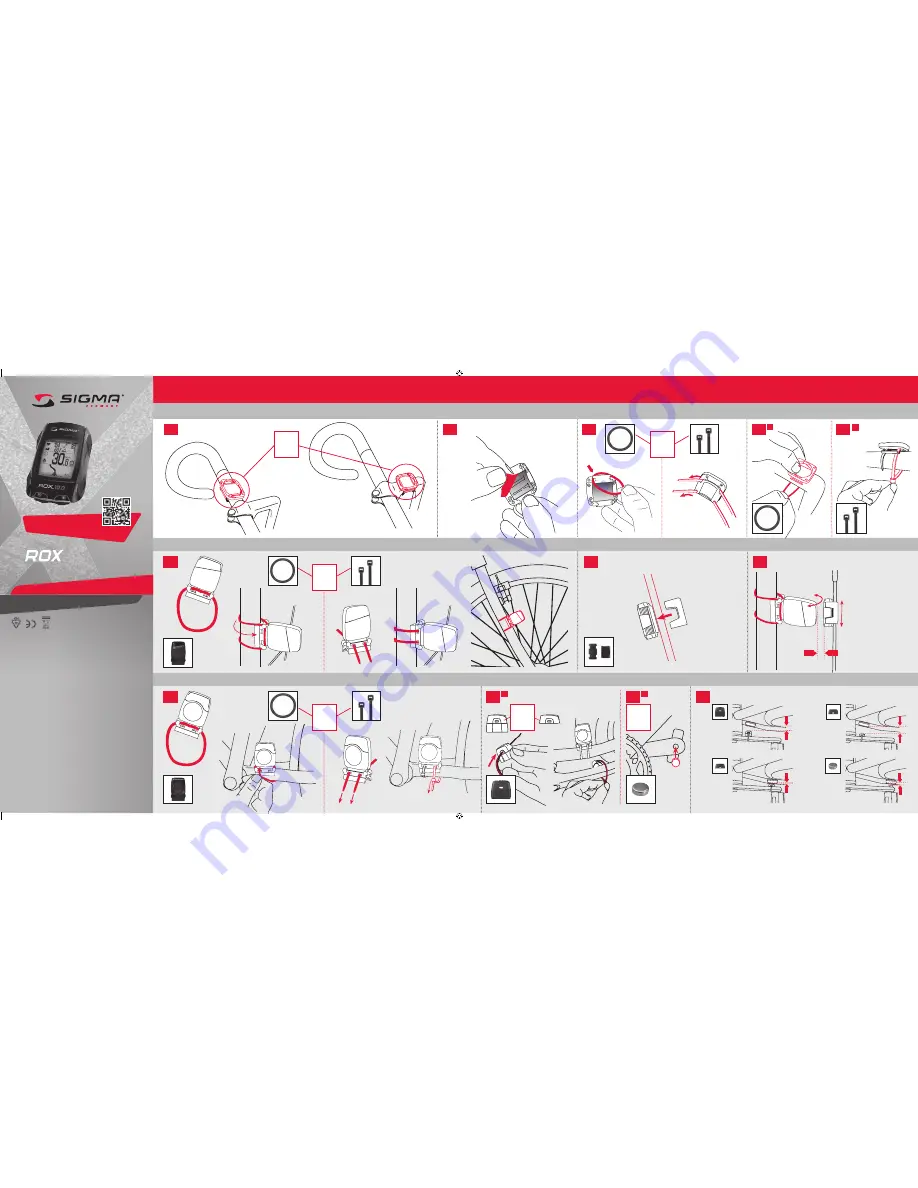
background image

Stem or handlebar?

inStallation oF the braCket

?

oder

or

ou

1.1

1.2

1.3

1.4

?

oder

or

ou

–  Remove the 
  yellow foil

1. inStallation oF the braCket

2.1

3.1

3.3

2.2

2.3

?

oder

or

ou

inStallation oF the poWer magnet

inStallation oF the CadanCe magnet

Max. 12 mm

adJuSting oF poWer magnet

adJuSting oF poWer magnet

–  In order to achieve the 
 

necessary 12 mm or less 


install the transmitter and 


the magnet closer to the 


wheel hub.

?

oder

or

ou

3. inStallation oF the WireleSS CadenCe tranSmitter

?

oder

or

ou

roX 10.0 gpS inStallation on the bike

2. inStallation oF the WireleSS Speed tranSmitter

1.4

A

B

Max.

 12 mm

Max.

 14 mm

3.2

3.2

A

B

Max.

 12 mm

Max.

 12 mm

10.0 GPS

INSTALLATION ON THE BIKE

SIGMA-ELEKTRO Gm

bH

Dr.-Julius

-Le

ber-Straße 15

D-67433 Neustadt

/We

instraße

SIGMA SPORT ASIA

4F, No.192, Zhonggong 2

nd

 Rd., 

Xitun Dist., Taichung City 407, Taiwan

SIGMA SPORT USA

3487 Swenson Ave.

St. Charles, IL 60174, U.S.A.

081000/1

FCC Statement

This device complies with

 part 15 of the FCC Rules.

 Operation is subject to th

e following two


conditi

ons: 

(1)   

This device may not cause harmful interf

erence, 


and

(2)   

this device must accept any interference rece

ived, including interf

erence 


that may cause undesired

 operation.

NOTE:

 This equipment has been tested

 and f

ound to comply with

 the li

mits for a Cl

ass B digita

device, pursuant to part 15 of the FCC Rules.

 These li

mits are designed to provide reasonable


protection aga

inst harmful interf

erence in a residential insta

llati

on. This equipment generates,


uses and can rad

iate rad

io frequency energy and, i

f not installed

 and used

 in accordance with


the instructi

ons, may cause harmful interf

erence to radio communicati

ons. 

However, there is no guarantee th

at interference will not occur in a particul

ar installati

on. 

If this equipment does cause harmful interf

erence to radio or televisi

on reception, which

 can 

be determined by turning th

e equipment off and on, th

e user is encouraged to try to correct


the interf

erence by one or more of the f

ollowing measures:

– Reori

ent or relocate the rece

iving antenna.

– Increase th

e separation between th

e equipment and rece

iver.

– Connect th

e equipment into an outlet on a circuit diff

erent from that to which

 the rece

iver 


is connected.

– Consult th

e dealer or an experi

enced rad

io/TV technici

an for h

elp.

Changes or mod

ificati

ons not expressly approved by th

e party responsible for compli

ance could 

void th

e user’s authority to operate th

e equipment.

This device complies with

 Industry Canada licence-exe

mpt RSS standard(s).


Operation is subject to th

e following two cond

itions:


(1)   

this device may not cause interference,


and 

(2)   

this device must accept any interference, includ

ing interference th

at may cause undesired 


operation of th

e device.

This Class d

igital apparatus compli

es with Canad

ian ICES-003.

FIND THE COMPLETE MANUAL, 
INSTALLATION AND SETTING VIDEOS 
UNDER: WWW.Sigma-Qr.Com/roX10

?

oder

or

ou

081000-1_Montageanleitung ROX 10.0_600x280.indd   1

12.06.13   14:30

Summary of Contents for ROX 10.0 G

Page 1: ...ovide reasonable protection against harmful interference in a residential installation This equipment generates uses and can radiate radio frequency energy and if not installed and used in accordance with the instructions may cause harmful interference to radio communications However there is no guarantee that interference will not occur in a particular installation If this equipment does cause ha...

Page 2: ...RANSMITTER BATTERY TYPE CR 2032 6 Battery change Load ROX 10 0 GPS INSTALLATION ON THE BIKE 4 1 5 1 4 2 4 3 4 4 Rub water or cardio gel on the electrodes ADJUSTING THE CHEST STRAP 4 ATTACHING the wireless heart rate transmitter 5 Installing the SIGMA ROX to the bracket CLICK PC USE OR AC DC 1 Installation of the bracket and sensors 2 Wake up ROX 10 0 GPS Press the key ENTER for 5 seconds Press ENT...

Page 3: ...TRACK NAVI TRAining analysis barometric compatible log DIGITAL wireless DIGITAL wireless DIGITAL wireless ready BIKE COMPUTER BLACK set GPS ...

Page 4: ... ...

Page 5: ...ters with the ROX 10 0 GPS 10 2 5 Synchronizing the transmitters 11 2 5 1 Synchronizing the speed 11 2 5 2 Synchronizing the cadence 11 2 5 3 Synchronizing the chest belt 11 3 Menu tree 12 4 Operating concept 13 4 1 ROX 10 0 GPS navigation principle 13 4 2 Button functions 14 4 3 Operating concept for the remaining menu 15 4 3 1 Top display segment 15 4 3 2 Bottom display segment 15 4 4 Training m...

Page 6: ... 25 5 6 2 Same track back function 25 5 6 3 Track found message 25 5 6 4 Off track alarm 25 5 6 5 Wrong direction message 25 5 6 6 Waypoint alarm 25 5 7 Analysis 25 6 Load track 26 6 1 Memory capacity for track data 26 6 1 1 Track data memory 26 6 2 Driven tracks 27 6 2 1 Start track 27 6 2 2 Show track 27 6 2 3 Show altitude profile 27 6 3 Stored tracks 28 6 3 1 Start track 28 6 3 2 Show track 28...

Page 7: ...7 9 1 Stopwatch 37 9 2 Countdown 37 9 3 Compass 37 10 Settings 38 10 1 Scale unit 38 10 2 Device 38 10 3 Bike 1 3 totals 39 10 3 1 Pairing with the ROX 10 0 GPS 40 10 3 2 Pairing power meters 40 10 3 3 Total Values 40 10 4 Altitude 41 10 5 User 41 10 6 Heart rate intensity zones 41 10 7 Heart rate target zone 42 10 8 Power target zone 42 10 9 GPS settings 42 10 10 Favorites 43 10 11 Firmware updat...

Page 8: ...com ROX 10 0 ROX 10 0 11 1 4 Training advice 48 11 2 Troubleshooting 49 11 3 Frequently asked questions 50 12 Technical data 52 12 1 Max min and default values 52 12 2 Temperature batteries 54 13 Warranty and guarantee 55 14 Index 57 ...

Page 9: ...h your new ROX 10 0 GPS The ROX 10 0 GPS is a GPS bike computer that provides you with a broad range of information both during and after your rides Speed time distance power and position altitude incline heart rate intensity zones and much more Download all information to a PC or Mac so that you can view and analyze your ride data Plan tracks with DATA CENTER 3 1 1 2 Contents ROX 10 0 GPS Black o...

Page 10: ...rent heart rate current cadence and current incline can be easily viewed on the large display The ROX 10 0 GPS is more than a classic bike computer It features three bike profiles a configurable automatic start stop function and three different altitude calibration methods 1 3 1 ANT speed transmitter optional accessory Use the ANT speed transmitter to precisely determine your speed and trip distan...

Page 11: ...tions that are most important to you during a ride Don t worry the ROX 10 0 GPS will record all functions in the background for post ride analysis This reduces the amount of clicking and lets you focus on your ride 1 3 6 PC Mac interface The ROX 10 0 GPS can be connected to a PC or Mac The micro USB cable supplied can be used to charge the ROX 10 0 GPS and transfer data between your computer and t...

Page 12: ... 0 GPS Charge the device using the micro USB cable and the USB port on your PC or use the wall charger supplied The process takes approximately three hours On the back of your ROX 10 0 GPS lift the rubber plug to expose the micro USB port 2 3 Initial use 1 Press and hold the ENTER button for five seconds 2 Press ENTER to change the language 3 Now press the and buttons to select your desired langua...

Page 13: ...eceiver usually synchronizes with the transmitter after five wheel rotations Spin the wheel until the current speed appears on the display 2 5 2 Synchronizing the cadence There are two options for synchronizing the cadence Start cycling the receiver usually synchronizes with the transmitter after five pedal rotations Turn the pedals until the current cadence appears on the display 2 5 3 Synchroniz...

Page 14: ...ture Altimeter Uphill Downhill Laps Show track Graph analysis Delete tour Bicycle Heart rate Uphill Downhill Bicycle Heart rate Time Power Temperature Altimeter Uphill Downhill Laps Show track Graph analysis Status info Battery GPS signal Memory Extras Stopwatch Countdown Compass Settings Scale unit Device Bike 1 3 totals Altitude User Intensity zone Target zone Power target zone GPS settings Favo...

Page 15: ...e tree diagram in section 3 Menu tree as a guide The navigation bar at the top of the ROX 10 0 GPS screen will help guide you through the menus The possible functions of the BACK and ENTER buttons are also displayed in the navigation bar Go to the next level down ENTER SELECT EDIT Go back to the next level up BACK Go to the next editable position NEXT Activate or deactivate a function ON OFF Scrol...

Page 16: ...wer change the value displayed or zoom out in Track Altitude View Enter button Press this button to access the submenus or zoom the top display data HR Alti Cad Slope Press and hold the button to turn the ROX 10 0 GPS on and off Simultaneously press the BACK and ENTER buttons to open the short menu Mode button Plus button Press this button to switch between the Bikecomputer Track View and Altitude...

Page 17: ...nd can be modified by pressing the and buttons Save your changes by pressing ENTER 4 3 1 Top display segment The top line of the upper display segment will change depending on which menu you are in The possible functions of the BACK and ENTER buttons will be displayed to assist you The second line of the top display segment always shows which menu submenu you are currently in 4 3 2 Bottom display ...

Page 18: ...en the different modes 4 4 1 Bikecomputer view mode The Bikecomputer view mode is divided into three display segments 4 4 1 1 Top display segment The first line displays the following values Battery status indicator or Battery charging GPS signal available Beneath these four current values are displayed Current heart rate only if you are wearing the chest belt Current cadence only if the cadence t...

Page 19: ...ee section 10 10 Favorites Press the and buttons to display the individual values 4 4 2 Track View mode In Track View mode up to six individually programmable values see section 10 10 Favorites are displayed in the upper display segment Press the ENTER button to navigate through the values Your route is graphically displayed in the bottom segment Press the and buttons to zoom the display 4 4 3 Alt...

Page 20: ...k View Altitude View and Lap Message view modes Before each ride choose favorites A or B using the short menu Preset functions for favorite A in Bikecomputer view mode 1 Trip distance 2 Exercise time 3 Average speed 4 Max speed 5 Max incline uphill 6 Trip distance uphill 7 Altitude ascent 8 Altitude profile 9 Temperature 10 Clock Preset functions for favorite B in Bikecomputer view mode 1 Trip dis...

Page 21: ...surement is determined by barometric air pressure Any change to the weather means a change to the air pressure which can lead to a change to your current altitude To offset these changes in air pressure you must enter a reference altitude into the ROX 10 0 GPS process known as calibration The ROX 10 0 GPS offers three types of calibration only one has to be used 1 Home altitude 1 3 The home altitu...

Page 22: ...he ROX 10 0 GPS is used to measure the air pressure This opening must not be covered Do not insert sharp objects into the measurement hole 5 3 Power calculation or measurement The ROX 10 0 GPS can calculate the power using of several parameters or power values sent via an ANT compatible power meter Please choose between power meter and formula under Settings Device Power Meter or Formula 5 3 1 Pow...

Page 23: ...ne 3 80 90 HRmax e g BE2 or development zone Intensity zone 4 90 100 HRmax e g CE or peak zone 5 5 Training 5 5 1 Using the short menu to select training settings You can use the short menu to select the following basic settings for your training Altitude Favorites A or B Load track Track settings reverse track on off same track back on off and track direction driving direction north Target zone a...

Page 24: ...ndication Driving direction means that the route is always in front of you North means that the track is always pointing north and the arrow rotates on the display in accordance with your ride direction This means that if you are cycling south the arrow on the display will point down 5 5 2 Starting logs To start logs for your training session press the START button A brief confirmation message Exe...

Page 25: ... km h Auto Pause appears on the display and restarts at speeds of over 2 2 km h auto start Note If you have stopped the device manually it will no longer automatically restart you must also manually restart it Auto pause function deactivated The exercise time starts as soon as you have pressed START and stops when you press STOP This enables you to record your heart rate even when resting for exam...

Page 26: ...You can use the lap function to start a new lap or interval after riding a certain distance or reaching a certain position This enables you to compare your performance on different sections with similar distances A training log must be started for the lap function to operate Press the LAP button to end the current lap and automatically start a new one The Lap Message view appears for eight seconds...

Page 27: ...route and is triggered if you leave it 5 6 5 Wrong direction message The ROX 10 0 GPS detects if you are riding in the wrong direction and indicates this message If a tour has been incorrectly stored start and end points mixed up you can use the Reverse track function see section 5 5 1 Using the short menu to select training settings to directly reverse the tour on the ROX 10 0 GPS Note Reverse tr...

Page 28: ...tore up to 100 training files The maximum storage period also depends on the log interval selected The log times in hours per log interval can be seen in the table Log interval Log time in hours 1 sec 8 12 00 2 sec 16 25 00 5 sec 41 04 00 10 sec 82 08 00 20 sec 164 16 00 30 sec 246 24 00 The log interval can be set at the menu path Settings Device see section 10 2 Device 6 1 1 Track data memory Th...

Page 29: ...ck to ride the selected track Once you have selected Start Track the display will automatically switch to the training menu in Track View mode and your ride will begin Follow the route shown on the display Press the and buttons to zoom in and out 6 2 2 Show track Select Show track to display the route for the selected tour Press the and buttons to zoom in and out Press BACK to return to the driven...

Page 30: ...These tracks can be loaded onto the ROX 10 0 GPS Further information about Data Center can be found in the Data Center instructions After selecting a track by pressing the ENTER button you have four options Start track Show track Show altitude profile Show details 6 3 1 Start track Select Start track to cycle the selected track Once you have selected Start track by pressing ENTER the track starts ...

Page 31: ...6 3 3 Show altitude profile Select Show altitude profile to view a graphical representation of the trip s altitude profile Press BACK to return to the stored tracks menu 6 3 4 Show details Select Show Details to see the following Trip distance Altitude ascent Ride Rating ...

Page 32: ...ata 7 2 Stored tours Stored tours provides an overview of your stored saved tours Use the and buttons to select the tour for which you want to view then press ENTER All the values for the selected tour are displayed These are divided into 11 sub items see section 7 3 Stored data You can delete individual tours Press the and buttons to select Delete tour then press ENTER The question Are you sure a...

Page 33: ...is divided into the following 11 areas 1 Bicycle 2 Heart rate 3 Time 4 Power 5 Temperature 6 Altimeter 7 Uphill 8 Downhill 9 Laps 10 Show track 11 Graph analysis Note Certain values heart rate power work cadence can only be determined when using the ANT heart rate transmitter ANT cadence transmitter and or ANT power meter ...

Page 34: ...age heart rate Max heart rate Average of the max heart rate Calories Time in target zone Time at intensity 1 Time at intensity 2 Time at intensity 3 Time at intensity 4 7 3 3 Tour data time The time menu displays the following values Start date Start time Exercise time Trip time Note Reset all data prior to the start of a ride to ensure proper start date and time 7 3 4 Tour data power The power me...

Page 35: ... Average altitude Average incline Average rise rate 7 3 7 Tour data uphill The uphill menu displays the following values Altitude ascent Max altitude Trip distance Trip time Average speed Average rise rate Max rise rate Average incline Max incline Average expansion 7 3 8 Tour data downhill The downhill menu displays the following values Altitude descent Trip distance Trip time Average speed Averag...

Page 36: ...distance 4 Distance since start 5 Avg lap speed 6 max lap speed 7 Avg heart rate per lap 8 Max heart rate per lap 9 Calories per lap 10 Avg lap cadence 11 Max lap cadence 12 Avg lap power 13 Max lap power 14 Avg lap altitude 15 Max lap altitude 16 Lap altitude 17 Lap altitude 18 Avg incline 19 Avg incline 7 3 10 Tour data show track Show track displays a graphical outline of your route 7 3 11 Tour...

Page 37: ... 1 Total values bicycle Displays the total values for the distance and trip time for each bike 7 4 2 Total values heart rate Displays the total calories for each bike 7 4 3 Total values uphill Displays the total values for the altitude ascent max altitude distance and trip time for each bike 7 4 4 Total values downhill Displays the total values for the altitude descent distance and trip time for e...

Page 38: ... and the USB port on your PC or the USB wall charger supplied The charge status is always shown at the top right of the display If the device is switched off the charge status will appear in the center of the display while the device is charging 8 2 GPS signal View information about the GPS signal Accuracy in meters feet Position coordinates Date and time Satellites and signal strength 8 3 Memory ...

Page 39: ...the STOP button to stop the stopwatch and ENTER to reset it to zero Press the and buttons to scroll through the list of laps 9 2 Countdown Use the countdown function to make sure you do not miss important events Press the ENTER button to pre program the countdown Press the and buttons as well as the ENTER button to set the time After setting the time start the countdown by pressing the START butto...

Page 40: ...its for the ROX 10 0 GPS Speed km h mph Distance km miles Altitude meter feet Temperature C F Weight kg lb Date DD MM YYYY MM DD YYYY Clock 24h 12h 10 2 Device Language Press the and buttons followed by ENTER to select the language for the ROX 10 0 GPS Log interval Press the and buttons followed by ENTER to select the recording interval 1 sec 2 sec 5 sec 10 sec 20 sec 30 sec for the ROX 10 0 GPS F...

Page 41: ...on as your training session starts My name Auto pause on off Target zone alarm on off Button tone on off System tone on off Contrast Press the and buttons followed by ENTER to set the contrast 1 4 on the ROX 10 0 GPS Backlight time Press the and buttons followed by ENTER to set the backlight time permanent 5 min on 2 min on 30 sec on for the ROX 10 0 GPS 10 3 Bike 1 3 totals This section is used t...

Page 42: ... press ENTER Press ENTER again to trigger the pairing process with the power meter Activate your power meter as described by the manufacturer usually by turning the pedals or the wheel Once the pairing process has successfully completed you can calibrate the power zero point automatically or manually Please note that this is not necessary for all power meters For additional information please refe...

Page 43: ...on you can also delete individual altitude measurement points Note The altitude points list stores a maximum of 20 altitude measurement points 10 5 User Use this area to set the following user data Gender male female Date of birth mm dd yyyy Body weight 40 400 lbs Body height 40 100 inches Shoulder width 15 30 inches Max HR 100 240 bpm 10 6 Heart rate intensity zones The ROX 10 0 GPS has four inte...

Page 44: ...ividual Off If the target zone is activated a zone indicator arrow next to the heart rate and an optional beep sound indicate if you are above or below the target zone in training mode 10 8 Power target zone Set the upper and lower limits of the power target zone function or deactivate the function The following values can be set On or off Lower limit and upper limit 10 9 GPS settings GPS on off G...

Page 45: ... then press ENTER 3 In the Bikecomputer view mode you can define up to 10 values and their display positions Press the and buttons to choose the position 1 10 in which the value should be displayed then confirm your selection by pressing ENTER Note Six functions 1A 3B can be selected in the Track View Altitude View and Lap Message view modes 4 Press and to select the function category then press E...

Page 46: ...HR max Calories Target zone Intensity zone Heart rate graph Time Exercise time Trip time Clock Date Countdown Power Current power 3s avg power 30s avg power Avg power Max power Work in kJ Current power in W kg Power target zone Temperature Current temperature Minimum temperature Maximum temperature Altitude Current altitude Incline in Rise rate Altitude profile Uphill Altitude ascent Max altitude ...

Page 47: ... per lap Calories per lap Avg cadence per lap Max cadence per lap Avg power per lap Max power per lap Altitude ascent per lap Altitude descent per lap Avg incline per lap Avg incline per lap Track View Altitude View Bicycle Current speed Avg speed Max speed Trip distance Expansion Avg expansion Current cadence Avg cadence Max cadence Heart rate Current heart rate Avg heart rate Max heart rate of t...

Page 48: ...n Time of arrival Distance to destination Direction Lap Lap number Lap time Lap distance Avg speed per lap Max speed per lap Avg heart rate per lap Max heart rate per lap Calories per lap Avg cadence per lap Max cadence per lap Avg power per lap Max power per lap Avg altitude per lap Max altitude Altitude ascent per lap Altitude descent per lap Avg incline per lap Avg incline per lap Lap Message L...

Page 49: ...3 Within the Data Center select the Firmware Update option and follow the on screen instructions Additional information can be found in the Data Center instruction manual After the update the ROX 10 0 GPS turns off 10 12 Factory settings Caution Resetting the ROX 10 0 GPS to factory settings resets all values to zero and restores initial factory settings Before restoring the factory settings downl...

Page 50: ...PX7 They can be used in the rain without risk of damage ANT heart rate transmitter Watertight up to 3 ATM and therefore suitable for many sporting activities General ANT wireless transmission does not work under water 11 1 3 Chest belt care optional accessory The COMFORTEX cloth chest belt is machine washable on the delicate cycle Conventional laundry detergent is recommended Note Bleach or deterg...

Page 51: ...under the menu path Settings GPS Settings Is it switched on Are you outdoors Does your ROX 10 0 GPS have satellite connection See section 8 2 GPS signal Please note that it can initially take approx 1 minute for a GPS signal to be received No cadence displayed Do you have both the ANT cadence transmitter and the magnet properly installed Has the ANT cadence transmitter been paired with the ROX 10 ...

Page 52: ... 10 0 GPS and reconnect it after 20 seconds Can another person with a different bike computer heart rate monitor cause interference The ANT transmitter work on a high digital frequency and are extremely resistant to electromagnetic interferences The pairing process assigns the transmitters to specific bikes All other ANT transmitters that are not paired are ignored in training mode This almost ent...

Page 53: ...uations and achieve an accuracy of one meter in the current altitude information a reference altitude should be entered before each trip Entering this reference altitude is known as calibration Data transfer between the ROX 10 0 GPS and the Data Center software does not work or is faulty or slow Please ensure that the ROX 10 0 GPS is installed in the device manager as a COM port Avoid connecting t...

Page 54: ...te bpm 30 240 Max heart rate bpm 30 240 of the max heart rate 12 240 Avg of the max heart rate 12 240 Calories kcal 0 99999 Time Exercise time mm ss x hhh mm ss 00 00 0 999 59 59 Trip time mm ss x hhh mm ss 00 00 0 999 59 59 Time hh mm ss 12 h 24 h 00 00 00 23 59 59 Date DD MM YYYY or mm dd yyyy 01 01 2011 31 12 2099 Countdown hh mm ss 00 00 00 09 59 59 Power Current power Watt 0 2000 3s avg power...

Page 55: ...ip distance downhill km mi 0 9999 99 Trip time downhill mm ss x hhh mm ss 00 00 0 999 59 59 Avg speed downhill mph 0 00 199 80 Max negative rise rate ft min 499 0 Avg incline downhill 99 5 0 Max incline downhill 99 0 Avg expansion downhill ft r 0 0 10 0 Status Battery status 0 100 GPS accuracy ft 0 GPS signal strength Navigation Time to destination estimated hh mm ss 00 00 00 99 59 59 Estimated ti...

Page 56: ...r lap ft 999 16 999 Altitude ascent per lap ft 0 99999 Altitude descent per lap ft 0 99999 Avg incline per lap 0 99 5 Average incline per lap 99 0 12 2 Temperature batteries Bike computer Ambient temperature 140 degrees F 14 degrees F ANT speed transmitter Ambient temperature 140 degrees F 14 degrees F Battery type CR 2032 ref no 00342 ANT cadence transmitter Ambient temperature 140 degrees F 14 d...

Page 57: ...disposed of in household waste Please take the device to an official waste collection point The CE declaration can be found at www sigmasport com This device complies with Part 15 of the FCC Rules and with RSS 210 of Industry Canada Operation is subject to the following two conditions 1 This device may not cause harmful interference 2 This device must accept any interference received including int...

Page 58: ...urning the equipment off and on the user is encouraged to try to correct the interference by one or more of the following measures Reorient or relocate the receiving antenna Increase the separation between the equipment and receiver Connect the equipment into an outlet on a circuit different from that to which the receiver is connected Consult the dealer or an experienced technician for help ...

Page 59: ...m 25 Operating concept 13 14 15 16 Optional accessories 8 P Pairing the sensors 10 40 PC interface 9 Power calculation 20 Power measurement 20 R Rechargeable battery 36 Restoring factory settings 47 ROX 10 0 functions 8 S Same track back function 25 Selecting the time zone 38 Selecting training settings 21 Setting bike 1 3 39 Setting the altitude 41 Setting the countdown 37 Setting the language 38...

Page 60: ...ntdown on off 39 Switching the target zone alarm on off 39 Synchronizing the transmitters 11 T Technical data 52 Total values 35 Track settings 22 Reverse track 22 Same track back 22 Track direction 22 Training 21 Displaying training parameters 24 Lap Message view 24 Starting logs 22 Stopping ending logs 22 Storing a log 22 Troubleshooting 49 W Water resistance 48 Waypoint alarm 25 Z Zoom function...

Reviews: