Installation
Page 3-4
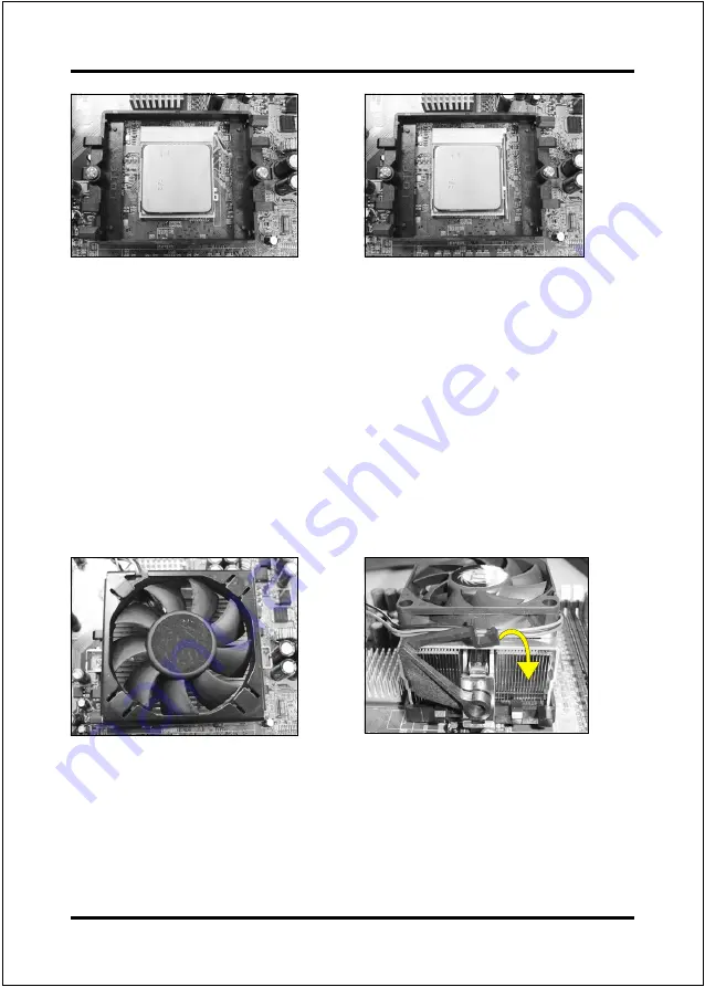
Step 5
Align pin 1 on the CPU with pin 1 on
the CPU socket as shown in the
illustration above. The CPU is keyed to
prevent incorrect insertion. Do not force
the processor into the socket. If it does
not go in easily, check for mis-orienta-
tion and reinsert the CPU.
Make sure the processor is fully
inserted into the socket.
<Figure 5>
<Figure 6>
Step 6
Close the socket by lowering and
locking the actuation lever.
Step 7
Apply thermal compound to the top of
the CPU and install the heatsink as
shown.
<Figure 7>
<Figure 8>
Step 8
Press the clips in the direction of the
arrows shown in Figure 8 to secure the
assembly to the CPU socket.
Summary of Contents for VIA K8T800
Page 6: ...LE Page Left Blank ...
Page 12: ...Introduction Page 1 6 Figure 5 System Block Diagram System Block Diagram ...
Page 17: ...Installation Page 3 1 Section 3 INSTALLATION ...
Page 18: ...Installation Page 3 2 Mainboard Layout ...
Page 80: ...Drivers Installation Page 6 8 ...
Page 88: ...Appendix C 2 ...


