background image

Intel

®

 Server System SR870BH2 


13 

Quick Start Guide   

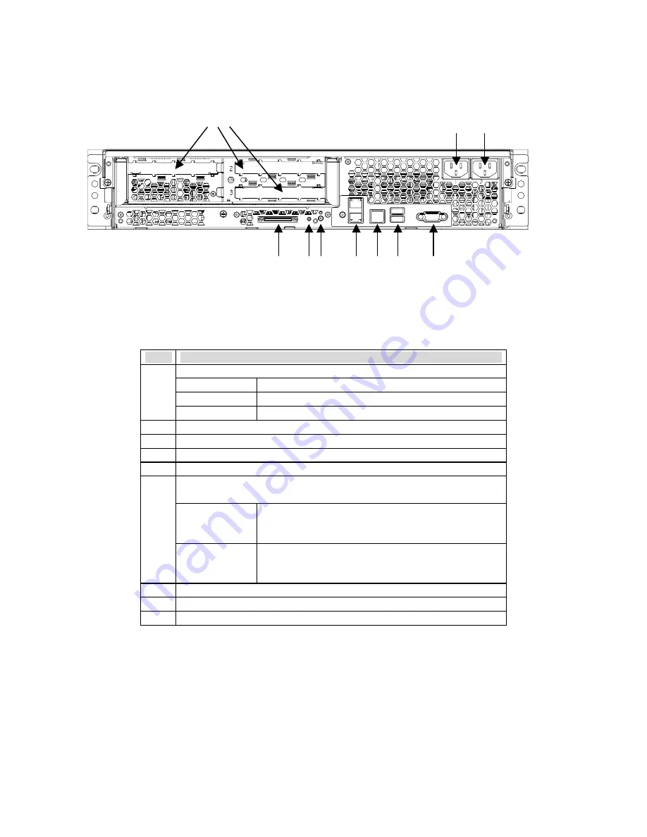
 Figure 5 shows the features found on the chassis back panel. 

Figure 5.  Chassis Back Features  


Table 4.  Back Panel Features 

Item


Description 

PCI Slots 

Slot 1 

100 MHz, 64-bit PCI-X slot, full length 

Slot 2 

100 MHz, 64-bit PCI-X slot, full length 

Slot 3 

133 MHz, 64-bit PCI-X slot, full length 

Two AC input power connectors  

External SCSI connector

1


System ID switch 

System ID LED (blue) 

Two LAN ports, RJ45 connector (LAN1 on bottom, LAN2 on top) 
LAN port LEDs: 

Green LED 

On – ethernet link is detected 
Off – no ethernet connection 
Blinking – ethernet link is active 

Green/Amber 
dual color LED 

Ethernet speed indicator 
Green On – 100 Mbps 
Amber On – 1000 Mbps 

G Serial 

port

2

, RJ45 connector 

Two USB 1.1 ports, 4-pin connectors (USB0 on bottom, USB1 on top) 

Video port, standard VGA compatible, 15-pin connector 


Notes:

  1.  External SCSI bus supports both LVDS and SE signals via the external SCSI 

connector. 


2.  EMP access is provided via shared serial port. 

A

1  2  3

B

1    

2

C

F

G

H

I

D E

A

1  2  3

B

1    

2

C

F

G

H

I

D E

Summary of Contents for SR870BH2 - Server Platform - 0 MB RAM

Page 1: ...Intel Server System SR870BH2 Quick Start Guide Order Number C43207 001 This guide contains basic instructions for setting up the system and accessing the Product Guide from the Resource CD...

Page 2: ...ation Intel Copyright 2000 2003 Intel Corporation All rights reserved No part of this document may be copied or reproduced in any form or by any means without prior written consent of Intel Intel Corp...

Page 3: ...Compatibility Notices International 7 Removing the Server from the Box 8 Selecting a Site 8 Checking Power Cords 9 Connections and Controls 10 Connecting the Monitor Keyboard and Mouse 14 Powering On...

Page 4: ...iv Intel Server System SR870BH2 Quick Start Guide This page intentionally left blank...

Page 5: ...hes 449 mm Depth 29 4 inches 747 mm Front clearance 3 inches 76 mm Side clearance 1 inch 25 mm Rear clearance 6 inches 152 mm Weight 1 65 lbs 30 kg Note 1 The system weight listed above is an estimate...

Page 6: ...t the interference by one or more of the following measures Reorient or relocate the receiving antenna Increase the separation between the equipment and the receiver Connect the equipment into an outl...

Page 7: ...otice above This is a Class A product based on the standard of the Voluntary Control Council for Interference by Information Technology Equipment VCCI If this equipment is used in a domestic environme...

Page 8: ...a properly earthed grounded three pronged power outlet In the United States and Canada a NEMA compliant 110 208 V outlet rated for 15 amps In other geographic areas a properly grounded earthed outlet...

Page 9: ...panel of the server does not completely remove AC power To completely remove AC power from the server you must unplug both AC power cords from the system or from the wall outlet Unplugging the cords...

Page 10: ...ecommendations In geographic regions that are susceptible to electrical storms we highly recommend that you plug the server into a surge suppressor EMI Information For information about complying with...

Page 11: ...eature Description Front Panel Switches and LED Indicators Toggles system power LED State ACPI Off Power off No On Power on No Off S4 S5 Yes A System Power switch and LED On S0 Yes B System Reset swit...

Page 12: ...Alarm Non Critical of redundant Pwr Flt redundant Fan Voltage and Temperature failures Indicates Hard drive subsystem fault status LED State Description Off Drive Missing Slot Empty Online Prepare for...

Page 13: ...m ID LED blue Two LAN ports RJ45 connector LAN1 on bottom LAN2 on top LAN port LEDs Green LED On ethernet link is detected Off no ethernet connection Blinking ethernet link is active F Green Amber dua...

Page 14: ...monitor keyboard and mouse have been connected 2 Plug the female ends of both AC power cords into the back of the chassis B 1 and 2 in Figure 5 3 Plug the male ends of the server AC power cords into...

Page 15: ...rompt to appear Shell 13 Mount the DVD CD RW device as block zero For information on how to mount this device see Mounting the DVD CD RW Device below 14 Boot the operating system that you want to run...

Page 16: ...ver System SR870BH2 EFI based utilities How to invoke the Resource CD menu 1 Insert the Resource CD into the server s DVD CD RW drive before booting to EFI Shell 2 Boot the system into EFI Shell the E...

Reviews: