Intel SC5650-DP Service Manual Download Page 82

Hot Swap Drive Cage Upgrade Install Instructions (optional)

64

Intel

®

 Server Chassis SC5650-DP/WS/BRP/UP Service Guide

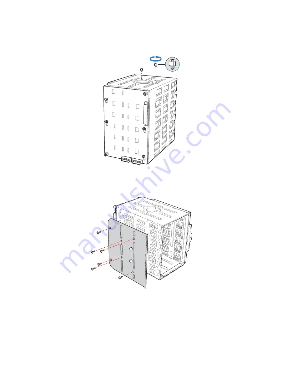
9. Remove the stud screws from the top of the hot swap drive cage.

Figure 78. Removing Stud Screws from Hot Swap Drive Cage

10. Attach the latch plate to the left side of the hot swap drive cage.

Figure 79. Attaching Latch Plate to Hot Swap Drive Cage

AF002935

TP01060

Summary of Contents for SC5650-DP

Page 1: ...Intel Server Chassis SC5650 DP WS BRP UP Service Guide A Guide for Technically Qualified Assemblers of Intel Identified Subassemblies Products Intel Order Number E55434 003...

Page 2: ...Intel may make changes to specifications and product descriptions at any time without notice Intel server boards contain a number of high density VLSI and power delivery components that need adequate...

Page 3: ...support intel com support motherboards server sb cs 010770 htm Consignes de s curit Lisez attention toutes les consignes de s curit et les mises en garde indiqu es dans ce document avant de suivre tou...

Page 4: ...or equipment damage can result Electrostatic discharge ESD and ESD protection ESD can damage disk drives boards and other parts We recommend that you perform all procedures in this chapter only at an...

Page 5: ...and product diagrams to help you identify components and their locations Chapter 2 provides instructions on adding and replacing components Use this chapter for step by step instructions and diagrams...

Page 6: ...d for ordering information for Intel products see http support intel com support motherboards server chassis sc5650 compat htm Additional Information and Software If you need more information about th...

Page 7: ...ion Guide http support intel com support motherboards server chassis sc5650 Hardware peripheral boards adapter cards and so forth and operating systems that were tested with this product Tested Hardwa...

Page 8: ...Preface viii Intel Server Chassis SC5650 DP WS BRP UP Service Guide...

Page 9: ...k Mounted Systems 10 Mechanical Locks 11 Accessories and Order Codes 11 Hardware Installations and Upgrades 13 Before You Begin 13 Tools and Supplies Needed 13 System References 13 Removing and Instal...

Page 10: ...stalling a Hot Swap Hard Drive 75 Removing a Hot swap Hard Drive 78 Rack Mount Kit Install Instructions optional 83 Before You Begin 83 Tools and Supplies Needed 83 System References 83 Setting up a R...

Page 11: ...atiques ESD 112 Autres risques 112 Espa ol 113 Informaci n de seguridad del servidor 113 Advertencias y precauciones sobre seguridad 113 Aplicaciones y usos previstos 114 Selecci n de la ubicaci n 114...

Page 12: ...ns Registrations Declarations 149 Product Regulatory Compliance Markings 149 FCC Verification Statement USA 152 Industry Canada ICES 003 153 Europe CE Declaration of Conformity 153 VCCI Japan 153 BSMI...

Page 13: ...e 18 Re installing PCI Card Guide into Chassis 21 Figure 19 Inserting Fixed Hard Drive Cage into Chassis DP WS BRP configuration only 22 Figure 20 Re attaching Drive Cage EMI Shield 23 Figure 21 Drive...

Page 14: ...d Power Supply in Chassis 49 Figure 62 Locking Fixed Power Supply into Chassis 50 Figure 63 Removing Power Supply Filler Panel 51 Figure 64 Inserting Additional Hot Swap Power Supply Module 51 Figure...

Page 15: ...or 78 Figure 96 Opening Drive Bay Access Door 78 Figure 97 Removing Drive Carrier from Hot Swap Drive Cage 79 Figure 98 Removing Hard Drive from Drive Carrier 79 Figure 99 Installing Hard Drive in Dri...

Page 16: ...xvi Intel Server Chassis SC5650 DP WS BRP UP Service Guide...

Page 17: ...urations 1 Table 2 Server Chassis Features 2 Table 3 Accessories and Order Codes 11 Table 4 DP 600 W Power Supply Output Capability 95 Table 5 600 W Power Supply Output Capability 96 Table 6 1000 W Po...

Page 18: ...xviii Intel Server Chassis SC5650 DP WS BRP UP Service Guide...

Page 19: ...family The type of server board supported depends on the configuration purchased See Table 1 for a list of the Intel server boards supported by each server chassis configuration AF000307 1 The Intel S...

Page 20: ...Intel validated PSU with integrated cooling fan 400 W PFC Intel validated PSU with integrated cooling fan System Cooling One tool less 120 mm chassis fan One tool less 120 mm PCI fan One tool less 92...

Page 21: ...17 8 in 45 2 cm x 9 256 in 23 5 cm x 19 in 48 3 cm Dimensions Rack 9 256 in 23 5 cm x 17 6 in 44 7 cm x 19 in 48 3 cm A 5 25 in Device Drive Bays B Front Panel C Drive Bay Access Door D Door Lock E Fr...

Page 22: ...is SC5650 DP WS BRP UP Service Guide Figure 3 Front View Components without Front Bezel Assembly A 5 25 in Device Drive Bays B 3 5 in Device Drive Bay C Hard Drive Cage D Drive Bay EMI Shield shown op...

Page 23: ...ce Bays C 3 5 in Device Bay D Drive Bay EMI Shield E Drive Cage Retention Mechanism F PCI Add in Card Guide G Front Panel USB Ports H Rear Tool less PCI Retention Mechanisms I Fan Duct System Fan Asse...

Page 24: ...Server Chassis Features 6 Intel Server Chassis SC5650 DP WS BRP UP Service Guide Back Panel Components...

Page 25: ...NOTE Fixed Power Supply shown Your Power Supply may vary depending on chassis configuration purchased C I O Shield NOTE I O connectors vary depending on the server board installed See your server boa...

Page 26: ...off or on C NMI Button Used to force system halt and dump memory contents to screen or file D Reset Button Reboots and initializes the system E F NIC 1 Activity LED NIC 2 Activity LED Continuous gree...

Page 27: ...age capable of supporting up to six cabled 3 5 in x 1 in hard drives Power requirements for each individual hard drive may limit the maximum number of drives that can be integrated into the server cha...

Page 28: ...tion and Software for a web link to a list of supported hardware Front Bezel Assembly The front bezel assembly provides a snap on design that allows for maximum airflow through the server chassis All...

Page 29: ...r of the chassis Figure 8 Mechanical Locks Accessories and Order Codes For a complete list of spares and accessories available for your chassis see http support intel com go serverbuilder Note AXX6DRV...

Page 30: ...Server Chassis Features 12 Intel Server Chassis SC5650 DP WS BRP UP Service Guide...

Page 31: ...om assume the reader is facing the front of the chassis as it would be positioned for pedestal operation Removing and Installing the Left Side Cover Warning This chassis must be operated with the left...

Page 32: ...er rearward to remove from chassis see letter C Figure 9 Removing Left Side Cover Installing the Left Side Cover Warning This chassis must be operated with the left side cover installed to ensure prop...

Page 33: ...in Appendix A Safety Information 2 Power down the server and unplug all peripheral devices and the AC power cable 3 Remove the left side cover For instructions see Removing the Left Side Cover 4 If it...

Page 34: ...s must be operated with the right side cover installed to ensure proper cooling Figure 12 Re installing Right Side Cover on Chassis 2 Reinstall the front bezel assembly For instructions see Installing...

Page 35: ...peripheral devices connected to the server Turn off the server 3 Disconnect the AC power cord 4 Remove the left side cover For instructions see Removing the Left Side Cover 5 Disengage the two bezel t...

Page 36: ...t side cover For instructions see Installing the Left Side Cover 3 Reconnect all peripheral devices and the AC power cable Power up the server Installing or Removing a Server Board Note The type of In...

Page 37: ...eld see letter A in the following figure Figure 15 Removing Drive Cage EMI Shield from Fixed Drive Cage DP WS BRP configuration shown 6 Disconnect cables from any installed fixed hard drives If necess...

Page 38: ...pull the fixed hard drive cage from the chassis see letter B Figure 16 Removing Fixed Hard Drive Cage DP WS BRP configuration shown 8 Remove any PCI add in boards that are present 9 For Intel Server B...

Page 39: ...hen tighten the screws firmly starting with the screws at the center of the server board If removing a server board disconnect all cables connected to the server board For additional removal instructi...

Page 40: ...bay slot of the chassis You should hear a click when the blue plastic retention mechanism locks into place Figure 19 Inserting Fixed Hard Drive Cage into Chassis DP WS BRP configuration only 13 If pr...

Page 41: ...en the thumb screw Figure 20 Re attaching Drive Cage EMI Shield 15 Re install the front bezel assembly For instructions see Removing and Installing the Front Bezel Assembly 16 Re install the left side...

Page 42: ...of supported hard drives Installing a Fixed Hard Drive Caution Fixed drives are NOT hot swappable Before removing or replacing the drive you must first take the server out of service turn off all per...

Page 43: ...he front bezel assembly For instructions see Removing the Front Bezel Assembly 5 Loosen thumb screw and remove the drive cage EMI shield see letter A in the following figure Figure 22 Removing Drive C...

Page 44: ...the following figure and pulling the PCI card guide outward see letter B Figure 23 Removing PCI Card Guide 8 Route the required power cables connectors P7 P10 for DP BRP WS P6 P8 and P10 P12 for UP f...

Page 45: ...tch the drive locking assembly for the drive bay you want to install a hard drive in Figure 25 Unlatching Drive Latch 10 Insert fixed hard drive into drive bay and push until it stops Ensure the power...

Page 46: ...latch in to lock hard drive into drive bay Figure 27 Latching Drive Latch 12 Install additional drives as necessary Warning You MUST populate drive bay slots 1 3 and 5 first Failure to do so could res...

Page 47: ...figure and data see letter B cables to each of the installed drives The cables route through the oval opening at the bottom of the fixed drive cage Figure 29 Cabling a Fixed Hard Drive 14 Re attach th...

Page 48: ...ee Installing the Left Side Cover 19 Plug all peripheral devices and the AC power cable back into the server Power up the server Removing a Fixed Hard Drive Caution Fixed drives are NOT hot swappable...

Page 49: ...ing door outward see letter B Figure 32 Removing Drive Cage EMI Shield from Chassis DP WS BRP configuration shown 6 Disconnect the data and power cables from the hard drive to be removed see letter A...

Page 50: ...Installing a Fixed Hard Drive for instructions Figure 34 Removing Fixed Hard Drive from Drive Bay 8 Re attach the drive cage EMI shield to the chassis and tighten the thumb screw Figure 35 Re install...

Page 51: ...er button and unplug the AC power cord from the system or wall outlet Installing a DVD ROM or CD ROM Drive 1 Observe the safety and ESD precautions listed in Appendix A Safety Information 2 Power down...

Page 52: ...e latch to the lock position see letter E Connect power P5 or P6connector from the power supply An additional 4 pin IDE male to SATA 15 poin power cables adapter may be needed if the CD ROM or DVD ROM...

Page 53: ...sted in Appendix A Safety Information 2 Power down the server and unplug all peripheral devices and the AC power cable 3 Remove the chassis cover For instructions see Removing the Left Side Cover 4 Re...

Page 54: ...nd remove a PCI add in board in the Intel Server Chassis SC5650 These instructions depend on the server board See your server board documentation to determine PCI add in board compatibility Caution Do...

Page 55: ...ce DP WS BRP configuration shown 5 If it is already not removed remove the PCI slot shield by pushing the shield out from the inside of the chassis Figure 41 Removing PCI Slot Shield 6 Remove a PCI ad...

Page 56: ...ing the Left Side Cover 11 Reconnect all peripheral devices and the AC power cable Power up the server Removing PCI Add in Boards Caution PCI add in boards can be extremely sensitive to electric stati...

Page 57: ...ation shown 5 Disconnect any cables that may be attached to the PCI add in board that needs to be removed 6 Firmly grab the PCI add in board by its top edge or upper corners and remove from the expans...

Page 58: ...stalled Caution The front panel board is NOT hot swappable Before removing or replacing the front panel board you must first take the server out of service turn off all peripheral devices connected to...

Page 59: ...letter A in the following figure securing the right side cover to the chassis Lift the right side cover off the chassis Figure 46 Removing Right Side Cover from Chassis 6 Remove the three screws secu...

Page 60: ...f the chassis see letter A in the following figure Disconnect the front panel cable see letter B and the chassis intrusion cable see letter C from the front panel board Figure 48 Removing Front Panel...

Page 61: ...t panel board Slide the new front panel board through the opening in the left side of chassis see letter C Figure 50 Installing Front Panel Board in Chassis 10 Use one hand to align the front panel bo...

Page 62: ...14 Reconnect all peripheral devices and the AC power cable Power up the server Replacing a System Fan Caution The system fan for the Intel Server Chassis SC5650 is NOT hot swappable Before removing or...

Page 63: ...ard S5500BC Remove the fan duct system fan assembly Figure 53 Removing Fan Duct System Fan Assembly DP WS BRP configuration 5 Disconnect the fan power cable from the server board see letter A in the f...

Page 64: ...om snap in bracket Figure 55 Removing Fan Duct System Fan Assembly UP configuration 7 For Intel Server Board S5500BC only install the fan guard For installation the new system fan in the snap in brack...

Page 65: ...into the snap in bracket on the chassis back panel Figure 58 Re installing Fan Duct System Fan Assembly UP configuration 10 Reconnect the fan cable to the server board Refer to the User Guide that cam...

Page 66: ...t first take the server out of service turn off all peripheral devices connected to the system turn off the system by pressing the power button and unplug the AC power cord from the system or wall out...

Page 67: ...power supply out of the chassis Figure 60 Removing Fixed Power Supply from Chassis 7 Insert the new fixed power supply in chassis Ensure the blue locking mechanism is still in the open position Make...

Page 68: ...ame with your Intel server board for appropriate power connections 10 Route the P5 and P6 cables for WS to the PCI Express graphic cards 11 Route the P9 and P10 for DP BRP WS P3 and P4 for UP cables t...

Page 69: ...ply Hazardous voltage current and energy levels are present inside the power supply There are no user serviceable parts inside it servicing of the power supply should be done only by technically quali...

Page 70: ...iceable parts inside it servicing of the power supply should be done only by technically qualified personnel 1 Observe the safety and ESD precautions listed in Appendix A Safety Information 2 Remove p...

Page 71: ...nd energy levels are present inside the power supply There are no user serviceable parts inside it servicing of the power supply should be done by technically qualified personnel 1 Observe the safety...

Page 72: ...if one is present 6 Disconnect all internal power cables from chassis components and server board 7 Remove two internal screws see letter A in the following figure securing hot swap power supply cage...

Page 73: ...69 Detaching Hot Swap Power Supply Cage from Rear of Chassis 9 Remove the two screws see letter A in the following figure attaching the rear support bracket to the old power supply cage Remove the re...

Page 74: ...age into chassis Secure back of hot swap power supply cage to chassis with five screws Note Ensure you route the power supply cables through the power supply opening in the chassis first before insert...

Page 75: ...er Guide that came with your Intel server board for appropriate power connections 14 Route the P5 and P6 cables to the PCI Express graphic cards 15 Route the P9 and P10 cables to the 5 25 in removable...

Page 76: ...S BRP UP Service Guide Figure 74 Re installing Hot Swap Power Supply Module s 18 Install the left side cover For instructions see Installing the Left Side Cover 19 Reconnect all peripheral devices and...

Page 77: ...sted in Appendix A Safety Information 2 Power down the server and unplug all peripheral devices and the AC power cable 3 Lay the chassis down on its right side 4 Insert rubber foot into chassis hole s...

Page 78: ...Hardware Installations and Upgrades 60 Intel Chassis SC5650 DP WS BRP UP Service Guide...

Page 79: ...formation and Software for a web link to a list of supported hard drives Before You Begin Before working with your server product review the important safety information listed in Appendix A Safety In...

Page 80: ...power cable 3 Remove the left side cover For instructions see Removing the Left Side Cover 4 Remove the front bezel assembly For instructions see Removing the Front Bezel Assembly 5 Loosen the thumb s...

Page 81: ...ee letter A in the following figure Once released pull the fixed hard drive cage from the chassis see letter B Figure 77 Removing Fixed Hard Drive Cage from Chassis DP WS BRP configuration shown 8 Gat...

Page 82: ...DP WS BRP UP Service Guide 9 Remove the stud screws from the top of the hot swap drive cage Figure 78 Removing Stud Screws from Hot Swap Drive Cage 10 Attach the latch plate to the left side of the ho...

Page 83: ...Service Guide 65 11 Attach the side filler panel to the right side of the hot swap drive cage Figure 80 Attaching Filler Panel to Hot Swap Drive Cage 12 Remove the two thumb screws that secure the ba...

Page 84: ...drive cage see letter A in the following figure and slide the fan bracket into position Replace the two thumb screws see letter B Caution The backplane may have slipped once the thumb screws were rem...

Page 85: ...Hot Swap Drive Cage Upgrade Install Instructions optional Intel Server Chassis SC5650 DP WS BRP UP Service Guide 67 Figure 83 Attaching Fan Bracket to Non Expanded Hot Swap Drive Cage AF003066 A B...

Page 86: ...ach the fan to the fan bracket by placing two corners of the fan into the two holding slots on the fan bracket Press the fan into the fan bracket until it clicks into place Caution Ensure the label an...

Page 87: ...Hot Swap Drive Cage Upgrade Install Instructions optional Intel Server Chassis SC5650 DP WS BRP UP Service Guide 69 Figure 85 Attaching Fan to Fan Bracket Non Expanded Hot Swap Drive Cage AF003067...

Page 88: ...nism locks into place Be sure to feed the fan cable through the slot first so it exits through the back of the drive cage Connect the fan cable to its connector on the server board Figure 86 Inserting...

Page 89: ...er card Warning It is critical that you connect the SAS SATA data cables correctly from the SAS SATA backplane to your server board or RAID controller card Failure to do so may result in data loss Not...

Page 90: ...ice Guide The SAS SATA connectors are laid out as follows on the SAS SATA backplane Figure 87 Layout of Cable Connectors on the SAS SATA Backplane Backplane without expander shown A SATA SAS hot swap...

Page 91: ...le see letter B to each appropriate SAS SATA connector on the SAS SATA backplane iii Connect the IPMB cable see letter C iv Connect the SES cable see letter D v Connect the fan power to the server boa...

Page 92: ...ii Connect the IPMB cable see letter C iv Connect the fan power to the server board For other Intel server boards refer to the Quick Start User s Guide that came with the server board Figure 89 Making...

Page 93: ...he fixed hard drive cage that shipped with your chassis with a SAS SATA hard drive cage If you are replacing a fixed hard drive see Removing a Fixed Hard Drive for instructions Note The Intel Server C...

Page 94: ...f the drive cage Figure 91 Releasing Drive Carrier from Hot Swap Drive Cage 3 Remove the four screws that attach the plastic retention device to the drive carrier Two screws are located on each side o...

Page 95: ...stalling Hard Drive into Drive Carrier 8 With the black lever in the fully open position insert the drive carrier into the hot swap drive cage The green latch at the front of the drive carrier must be...

Page 96: ...l 78 Intel Server Chassis SC5650 DP WS BRP UP Service Guide 9 Close the drive bay access door Figure 95 Closing Drive Bay Access Door Removing a Hot swap Hard Drive 1 Open the drive bay access door Fi...

Page 97: ...n the following figure Pull out on the black lever see letter B to slide the drive carrier from the hot swap drive cage Figure 97 Removing Drive Carrier from Hot Swap Drive Cage 3 Remove the four scre...

Page 98: ...the screws removed in the previous step Note If you are not installing a new drive place a plastic retention device into the drive carrier using the four screws you removed from the hard drive Figure...

Page 99: ...RP UP Service Guide 81 Note For proper airflow the drive carrier must be replaced in the chassis even if no hard drive is installed in it Figure 101 Re installing Drive Carrier in Hot Swap Drive Cage...

Page 100: ...Hot Swap Drive Cage Upgrade Install Instructions optional 82 Intel Server Chassis SC5650 DP WS BRP UP Service Guide...

Page 101: ...n Tools and Supplies Needed Phillips cross head screwdriver 1 bit and 2 bit Needle nosed pliers Anti static wrist strap and conductive foam pad recommended System References All references to the left...

Page 102: ...rubber foot see letter A in the following figure Remove the rubber foot from the chassis hole see letter B Repeat process for remaining feet Figure 103 Removing Chassis Feet 5 Remove the top side cove...

Page 103: ...s SC5650 DP WS BRP UP Service Guide 85 6 Remove any PCI add in boards Remove the PCI card guide by pressing in on the blue tabs see letter A in the following figure and pulling the PCI card guide outw...

Page 104: ...P UP Service Guide 7 Remove plastic filler panel from chassis by pushing on interior tab see letter A in the following figure and sliding filler panel towards rear of chassis see letter B Figure 106 R...

Page 105: ...Service Guide 87 8 Remove the three plastic plugs from the left side of chassis Figure 107 Removing Plastic Plugs DP WS BRP configuration shown 9 Remove two screws from the left and right sides of ch...

Page 106: ...0 DP WS BRP UP Service Guide 10 Remove the four plastic plugs from the top side cover Figure 109 Removing Plastic Plugs from Top Side Cover 11 Install rack handle on left side cover using four 6 32 sc...

Page 107: ...el assembly Affix front panel label see letter A in the following figure to the front panel Figure 111 Affixing Label to Front Panel 13 Install top side cover on chassis Warning This chassis must be o...

Page 108: ...tel Server Chassis SC5650 DP WS BRP UP Service Guide 14 Detach inner rack rail from rack rail assembly Press tab on inside of rack rail to release rack rail from rack rail assembly Figure 113 Detachin...

Page 109: ...per side to chassis with four 6 32 screws Figure 114 Attaching Inner Rack Rails to Chassis DP WS BRP configuration shown 16 Attach outer rack rails to rack uprights Ensure the screws two per outer ra...

Page 110: ...Rack Mount Kit Install Instructions optional 92 Intel Server Chassis SC5650 DP WS BRP UP Service Guide Figure 115 Attaching Outer Rack Rails to Rack Uprights TP01056 B C A...

Page 111: ...93 17 Install chassis into rack Warning Safe handling and lifting of this system requires TWO people Figure 116 Installing Chassis into Rack 18 Reconnect all peripheral devices and the AC power cable...

Page 112: ...Rack Mount Kit Install Instructions optional 94 Intel Server Chassis SC5650 DP WS BRP UP Service Guide...

Page 113: ...iguration 600 W PFC Intel validated PSU with integrated cooling fan You can add one additional 600 W PSU for redundancy BRP configuration 1000 W PFC Intel validated PSU with integrated cooling fan WS...

Page 114: ...100 127V at 50 60 Hz 15 Arms max 200 240V at 50 60 Hz 7 Arms max 1000 W Single Power Supply Output Voltages The following table lists the total amperage available from the power subsystem for each vol...

Page 115: ...bility Voltage Maximum Current 3 3 V 20 A 5 0 V 20 A 5 V Standby 2 5 A 12 0 V1 16 A 12 0 V2 16 A 12 0 V 0 5 A Table 8 System Environmental Specifications Temperature Non operating Operating 40 to 70 C...

Page 116: ...Technical Reference 98 Intel Server Chassis SC5650 DP WS BRP UP Service Guide...

Page 117: ...g product certifications and approvals Use only the described regulated components specified in this guide Use of other products components will void the UL Listing and other regulatory approvals of t...

Page 118: ...cluding direct sunlight and radiators Away from sources of vibration or physical shock Isolated from strong electromagnetic fields produced by electrical devices In regions that are susceptible to ele...

Page 119: ...viceable parts Do not open the power supply Hazardous voltage current and energy levels are present inside the power supply Return to manufacturer for servicing When replacing a hot plug power supply...

Page 120: ...en handling parts Always handle boards carefully They can be extremely sensitive to ESD Hold boards only by their edges After removing a board from its protective wrapper or from the server place the...

Page 121: ...ch qualifizierte Personen erfolgen Um die Einhaltung der vorhandenen Zulassungen und Genehmigungen f r das Produkt zu gew hrleisten sind die Richtlinien in diesem Handbuch sowie die Montageanleitungen...

Page 122: ...Ersch tterungsquellen Abgeschirmt von starken elektromagnetischen Feldern die durch elektrische Ger te erzeugt werden In gewittergef hrdeten Gebieten sollten Sie das System an einen berspannungsschutz...

Page 123: ...ie folgenden Hinweise Halten Sie beim Transportieren und Anheben von Ger ten die rtlichen Gesundheits und Sicherheitsvorschriften ein Verwenden Sie mechanische oder andere geeignete Hilfsmittel zum Tr...

Page 124: ...chicken Sie das Ger t f r Wartungsarbeiten an den Hersteller zur ck Wenn Sie ein hot plug f higes Netzteil austauschen ziehen Sie dessen Netzkabel ab bevor Sie es aus dem Server ausbauen Zur Vermeidun...

Page 125: ...statische Entladungen k nnen zur Besch digung von Festplatten Platinen und anderen Komponenten f hren Daher sollten Sie alle Arbeiten an einer ESD Workstation ausf hren Steht ein solcher Arbeitsplatz...

Page 126: ...System nur mit angebrachten Geh useabdeckungen betrieben werden Die Inbetriebnahme des Systems ohne Abdeckung kann zur Besch digung von Systemkomponenten f hren So bringen Sie die Abdeckung wieder an...

Page 127: ...es produits composants annulera la liste UL et les autres approbations r glementaires du produit et le produit peut ne pas tre conforme aux autres lois et r glementations locales applicables au produi...

Page 128: ...radiateurs l cart des sources de vibration ou des chocs physiques Isol des champs lectromagn tiques importants produits par des appareils lectriques Dans les r gions sujettes aux orages magn tiques n...

Page 129: ...ation chaud d branchez le cordon du bloc d alimentation en cours de remplacement avant de le retirer du serveur Pour viter tout risque d lectrocution mettez le syst me hors tension et d branchez les c...

Page 130: ...lique non peinte de votre serveur lorsque que vous manipulez les pi ces Manipulez toujours les cartes avec pr caution Elles peuvent tre extr mement sensibles aux ESD Ne tenez les cartes que par leurs...

Page 131: ...Intel En el caso de que haya diferencias entre la informaci n para un producto en particular contenida en este documento y la informaci n proporcionada con dicho producto o en el sitio Web la documen...

Page 132: ...taci n Bien ventilada y alejada de fuentes de calor incluida la luz solar directa y los radiadores Alejada de fuentes de vibraci n o de golpes f sicos Aislada de campos electromagn ticos producidos po...

Page 133: ...reposo o stand by NO DESCONECTA completamente la alimentaci n de CA del sistema ya que el modo de reposo de 5 V sigue activo mientras el sistema est enchufado Para desconectar el sistema debe desenchu...

Page 134: ...esconecte todos los cables y l neas de telecomunicaci n que est n conectados al sistema Guarde todos los tornillos o elementos de fijaci n cuando retire las cubiertas de acceso Cuando termine de opera...

Page 135: ...con el lado de los componentes hacia arriba sobre una superficie con toma de tierra y sin carga est tica Utilice una almohadilla de espuma conductora si dispone de ella pero nunca el envoltorio de la...

Page 136: ...dispositivos l ser Precauci n Para evitar el riesgo de la exposici n a radiaciones o de da os personales No abra la caja de ning n perif rico o dispositivo l ser Los perif ricos o dispositivos l ser...

Page 137: ...Intel Server Chassis SC5650 DP WS BRP UP Service Guide 119...

Page 138: ...120 Intel Server Chassis SC5650 DP WS BRP UP Service Guide...

Page 139: ...Intel Server Chassis SC5650 DP WS BRP UP Service Guide 121...

Page 140: ...122 Intel Server Chassis SC5650 DP WS BRP UP Service Guide...

Page 141: ...Intel Server Chassis SC5650 DP WS BRP UP Service Guide 123...

Page 142: ...124 Intel Server Chassis SC5650 DP WS BRP UP Service Guide...

Page 143: ...or power supply The power cord s is considered the disconnect device to the main AC power The socket outlet that the system plugs into shall be installed near the equipment and shall be easily access...

Page 144: ...rocessor and heatsink may be hot if the system has been running Also there may be sharp pins and edges on some board and chassis parts Contact should be made with care Consider wearing protective glov...

Page 145: ...tems zu unterbrechen Die Stromkabel sind das Unterbrechungsger t zur Hauptstromquelle Die Steckdose in die das System gesteckt wird sollte sich in der N he des Ger tes befinden und leicht zug nglich s...

Page 146: ...Um die Abdeckung wieder anzubringen 1 Vergewissern Sie sich da Sie keine Werkzeuge oder Teile im Innern des Systems zur ckgelassen haben 2 berpr fen Sie alle Kabel Zusatzkarten und andere Komponenten...

Page 147: ...zkabeln zu gew hrleisten da der Stromanschlu des Produkts haupts chlich ber die Kabel unterbrochen wird Le bloc d alimentation de ce produit ne contient aucune pi ce pouvant tre r par e par l utilisat...

Page 148: ...a t install sur l arri re du syst me d verrouillez le et retirez le 2 Retirez toutes les vis des panneaux et mettez les dans un endroit s r 3 Retirez les panneaux Afin de permettre le refroidissement...

Page 149: ...x orages magn tiques il est recomand de brancher votre syst me un supresseur de surtension et de d brancher toutes les lignes de t l communications de votre modem durant un orage Muni d une prise mura...

Page 150: ...a una mu equera antiest tica sujetada a la toma de tierra del chasis o a cualquier tipo de superficie de metal sin pintar 6 No ponga en marcha el sistema si se han extra do las tapas del chasis Despu...

Page 151: ...no de trabajo normal Escoja un lugar Limpio y libre de part culas en suspensi n salvo el polvo normal Bien ventilado y alejado de fuentes de calor incluida la luz solar directa Alejado de fuentes de v...

Page 152: ...late sul retro del sistema 5 Qualora si tocchino i componenti proteggersi dallo scarico elettrostatico SES portando un cinghia anti statica da polso che attaccata alla presa a terra del telaio del sis...

Page 153: ...duttore Il sistema progettato per funzionare in un ambiente di lavoro tipo Scegliere una postazione che sia Pulita e libera da particelle in sospensione a parte la normale polvere presente nell ambien...

Page 154: ...136 Intel Server Chassis SC5650 DP WS BRP UP Service Guide...

Page 155: ...re parts A searchable knowledgebase to search for product information throughout the support site 2 If you are still unable to obtain a solution to your issue send an email to Intel s technical suppor...

Page 156: ...Getting Help 138 Intel Server Chassis SC5650 DP WS BRP UP Service Guide...

Page 157: ...ide a brief description below See the last page for space to include a detailed problem description ____________________________________________________________________ _______________________________...

Page 158: ..._________________________________ DIMM4B MB and Vendor part number __________________________________ Operating System Information Operating System ____________________________________________________...

Page 159: ...essional Edition____________________________ Intel Management Module Advanced Edition _____________________________ Control Panel Information Standard Control Panel ___________________________________...

Page 160: ...______________________________ ____________________________________________________________________ ____________________________________________________________________ _______________________________...

Page 161: ...Product is defective transportation charges for the return of Product to buyer within the USA will be paid by Intel For all other locations the warranty excludes all costs of shipping customs clearan...

Page 162: ...y costs of recovering reprogramming or reproducing any program or data stored in or used with a system containing this product Some jurisdictions do not allow the exclusion or limitation of incidental...

Page 163: ...s for the remainder of the original warranty period Telephone Support If you cannot find the information you need on Intel s World Wide Web site http www intel com call your local distributor or an In...

Page 164: ...Warranty 146 Intel Server Chassis SC5650 DP WS BRP UP Service Guide...

Page 165: ...processor used on this server board The final configuration of your end system product may require additional EMC compliance testing For more information please contact your local Intel representative...

Page 166: ...n a compatible Intel host system For information on compatible host system s refer to Intel s Server Builder Web site or contact your local Intel representative FCC ICES 003 Emissions USA Canada Verif...

Page 167: ...Conformity New Zealand BSMI Certification Taiwan GOST R Certification License Russia Belarus Certification License Belarus RRL Certification Korea IRAM Certification Argentina CNCA Certification Chin...

Page 168: ...ss A Canada CANADA ICES 003 CLASS A CANADA NMB 003 CLASS A C Tick Mark Australia New Zealand VCCI Marking Class A Japan BSMI Certification Number Class A Warning Taiwan GOST R Marking Russia RRL MIC M...

Page 169: ...Intel Server Chassis SC5650 DP WS BRP UP Service Guide 151 China Compulsory Certification Mark China Table 9 Product Regulatory Compliance Markings Regulatory Compliance Region Marking...

Page 170: ...will not occur in a particular installation If this equipment does cause harmful interference to radio or television reception which can be determined by turning the equipment off and on the user is...

Page 171: ...03 of the Canadian Department of Communications Europe CE Declaration of Conformity This product has been tested in accordance to and complies with the Low Voltage Directive 73 23 EEC and EMC Directiv...

Page 172: ...Intel Corporation Refer to country of origin marked on product CNCA CCC China The CCC Certification Marking and EMC warning is located on the outside rear area of the product Regulated Specified Compo...

Page 173: ...ing of any one device is 19 watts Total server configuration is not to exceed the maximum loading conditions of the power supply Restriction of Hazardous Substances RoHS Compliance Intel has a system...

Page 174: ...156 Intel Server Chassis SC5650 DP WS BRP UP Service Guide...

Reviews: