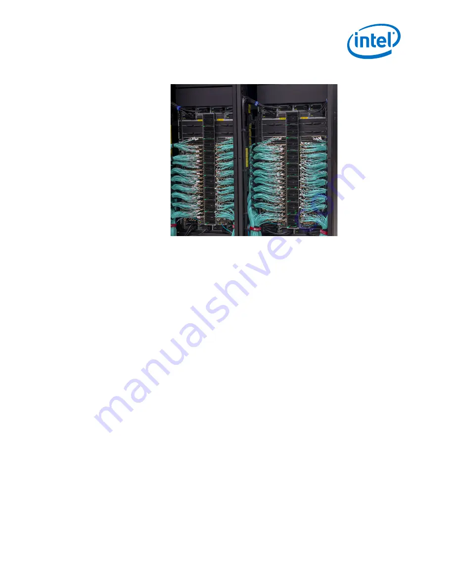
Figure 73.
Tying Off All Cables
Director Switch Cable Management—Intel
®
Omni-Path Fabric
Intel
Omni-Path Fabric Switches Hardware
June 2019
Installation Guide
Doc. No.: H76456, Rev.: 10.0
91
Page 1: ...Intel Omni Path Fabric Switches Hardware Installation Guide Rev 10 0 June 2019 Doc No H76456 Rev 10 0...
Page 2: ...y contain design defects or errors known as errata which may cause the product to deviate from published specifications Current characterized errata are available on request Intel technologies feature...
Page 3: ...ement Configuration on page 75 was updated to use the boot command moduleip April 2018 7 0 Added Figure 57 48 Port Leaf Module Port Numbering Added Q7 BIOS Update on page 86 April 2017 6 0 Updated Air...
Page 4: ...32 2 2 2 Check the Installation Site 32 2 2 3 Mark the Rack 32 2 3 Intel Omni Path Fabric Edge Switch Installation 33 2 3 1 Mounting Hardware Kit Contents 33 2 3 2 Rack Mounting 33 2 3 3 Installing t...
Page 5: ...Component LEDs 75 2 8 1 Edge Switch LEDs 76 2 8 2 Director Class LEDs 79 Appendix A Q7 BIOS Update 86 A 1 Before Getting Started 86 A 1 1 Prior to Upgrading 86 A 2 Displaying the Current Version 86 A...
Page 6: ...Unpacking the Switch 1 46 27 Unpacking the Switch 2 47 28 Unpacking the Switch 3 48 29 Unpacking the Switch 4 48 30 Unpacking the Switch 5 49 31 Unpacking the Switch 6 50 32 Unpacking the Switch 7 51...
Page 7: ...7 62 Activating the FM Enable Switch LED 78 63 Power Supply LEDs 79 64 Airflow Direction LED 79 65 Management Module LEDs 80 66 Leaf Module LEDs 81 67 Spine Module LEDs 82 68 SEEB Module LEDs 83 69 Di...
Page 8: ...Tables 1 Cable Bend Radius Guidelines 30 Intel Omni Path Fabric Tables Intel Omni Path Fabric Switches Hardware Installation Guide June 2019 8 Doc No H76456 Rev 10 0...
Page 9: ...qualified personnel Intel Omni Path Documentation Library Intel Omni Path publications are available at the following URLs Intel Omni Path Switches Installation User and Reference Guides http www int...
Page 10: ...are Managing a switch using GUI Installing switch firmware managed switches Describes the graphical user interface GUI of the Intel Omni Path Fabric GUI This document provides task oriented procedures...
Page 11: ...unning Docker and Singularity containers on Linux based computer platforms that incorporate Intel Omni Path networking technology Writing management applications that interface with Intel OPA Intel Om...
Page 12: ...ates a hyperlink jump to a figure table or section in this guide Links to websites are also shown in blue For example See License Agreements on page 13 for more information For more information visit...
Page 13: ...mblies used in the switch chassis are ESD sensitive Observe ESD handling procedures when handling any assembly used in the switch chassis License Agreements This software is provided under one or more...
Page 14: ...lass Switch 100 Series This manual is organized as follows This Introduction describes the product safety information Installation describes the hardware installation and initial configuration tasks A...
Page 15: ...Statement 1 1 1 1 Introduction Intel Omni Path Fabric Intel Omni Path Fabric Switches Hardware June 2019 Installation Guide Doc No H76456 Rev 10 0 15...
Page 16: ...Intel Omni Path Fabric Introduction Intel Omni Path Fabric Switches Hardware Installation Guide June 2019 16 Doc No H76456 Rev 10 0...
Page 17: ...Statement 2 1 1 2 Introduction Intel Omni Path Fabric Intel Omni Path Fabric Switches Hardware June 2019 Installation Guide Doc No H76456 Rev 10 0 17...
Page 18: ...Intel Omni Path Fabric Introduction Intel Omni Path Fabric Switches Hardware Installation Guide June 2019 18 Doc No H76456 Rev 10 0...
Page 19: ...Statement 3 1 1 3 Introduction Intel Omni Path Fabric Intel Omni Path Fabric Switches Hardware June 2019 Installation Guide Doc No H76456 Rev 10 0 19...
Page 20: ...Statement 4 1 1 4 Intel Omni Path Fabric Introduction Intel Omni Path Fabric Switches Hardware Installation Guide June 2019 20 Doc No H76456 Rev 10 0...
Page 21: ...Introduction Intel Omni Path Fabric Intel Omni Path Fabric Switches Hardware June 2019 Installation Guide Doc No H76456 Rev 10 0 21...
Page 22: ...Statement 5 1 1 5 Intel Omni Path Fabric Introduction Intel Omni Path Fabric Switches Hardware Installation Guide June 2019 22 Doc No H76456 Rev 10 0...
Page 23: ...Introduction Intel Omni Path Fabric Intel Omni Path Fabric Switches Hardware June 2019 Installation Guide Doc No H76456 Rev 10 0 23...
Page 24: ...Statement 6 1 1 6 Intel Omni Path Fabric Introduction Intel Omni Path Fabric Switches Hardware Installation Guide June 2019 24 Doc No H76456 Rev 10 0...
Page 25: ...Statement 7 1 1 7 Introduction Intel Omni Path Fabric Intel Omni Path Fabric Switches Hardware June 2019 Installation Guide Doc No H76456 Rev 10 0 25...
Page 26: ...Intel Omni Path Fabric Introduction Intel Omni Path Fabric Switches Hardware Installation Guide June 2019 26 Doc No H76456 Rev 10 0...
Page 27: ...Introduction Intel Omni Path Fabric Intel Omni Path Fabric Switches Hardware June 2019 Installation Guide Doc No H76456 Rev 10 0 27...
Page 28: ...to the following conditions NOTE Use a rack grounding kit and a ground conductor that is carried back to earth or to another suitable building ground Ground the equipment rack to earth ground NOTE Pr...
Page 29: ...ps to avoid injuring cables Keep all ports and connectors free of dust Untwisted Pair UTP cables can build up Electrostatic Discharge ESD charges when being placed into a new installation Before insta...
Page 30: ...ble Table 1 Cable Bend Radius Guidelines Intel Omni Path Copper Cable 100 Series American Wire Gauge AWG Size Cable Bend Radius 26 69 mm 30 66 mm Intel Omni Path Active Optical Cable 100 Series Gauge...
Page 31: ...equirements for the UPS Transition time the time necessary for the UPS to transfer from utility power to full load battery power The longest potential time period the UPS might be required to supply b...
Page 32: ...binet has a full earth ground to provide reliable grounding There is enough room to work on the equipment The equipment will have enough clearance for front and rear access The cables can be accessed...
Page 33: ...e called out In a standard depth rack the distance between the front and back mounting posts is 28 700 mm Mounting rails for the switch are adjustable to accommodate racks with 26 32 between mounting...
Page 34: ...e port side rails using four 4 M6 screws a Torque screws to 30 in lb Note the orientation of mounting rails in the following figure The rails are shown from the front side of the rack Figure 7 Install...
Page 35: ...ack 3 The rails are designed for different mounting positions from flush mount to recessed in 1 inch increments as shown in the following figure Installation Intel Omni Path Fabric Intel Omni Path Fab...
Page 36: ...from the switch hat section Figure 10 Rail Adjustment Notches 5 Slide the switch to the desired depth in the rack The switch is adjustable in increments of 1 inch When the switch is at the proper dept...
Page 37: ...itional considerations should be considered The mounting rails supplied with the edge switch are adequate for closing off the left and right side spaces on the cabinet from the U increment the edge sw...
Page 38: ...k until it stops against the edge switch a Baffle Extension s Each baffle i e top and bottom has an extension shown in yellow below If not pre configured insert 4 screws 2 on each side to secure the e...
Page 39: ...baffle clamp one on each side as shown 1 Unscrew the end of the rail post Figure 13 Remove Rail Post 2 Slide the clamp into place on the top and bottom baffles Figure 14 Insert Clamp on Baffles 3 Pus...
Page 40: ...6 Reattach the Rail Post Installing the Switch Fascia The Edge switch fascia guards against ESD as well as accidental contact with the fans and power supplies 2 3 4 Intel Omni Path Fabric Installation...
Page 41: ...the procedure to reverse the airflow on the switch fan assembly from the default port side exhaust position Tools Required ESD wrist strap 0 Phillips screwdriver Procedure NOTE Before removing the cov...
Page 42: ...up and rotate the fan assembly 180 degrees as shown in the following figure Figure 20 Fan Assembly Rotation 3 Lower the fan assembly straight down The airflow direction indicators should now face towa...
Page 43: ...ment Module into an existing externally managed edge switch Figure 22 Q7 Management Module Tools Required ESD wrist strap 0 Phillips screwdriver Regular screwdriver Procedure NOTE Before removing the...
Page 44: ...proximately a 45 degree angle slide the connector into module slot Make certain to line up the notch on the module and the connector see following figure Figure 24 Installing the Q7 Module 3 Once the...
Page 45: ...Kit contains Support Shelf 1 Baffles 2 10 Mounting screws 10 Mounting nuts M6 Mounting Screws Unpacking the Switch NOTE Set aside packaging materials in the event that the switch requires return ship...
Page 46: ...Figure 26 Unpacking the Switch 1 1 Remove the banding Intel Omni Path Fabric Installation Intel Omni Path Fabric Switches Hardware Installation Guide June 2019 46 Doc No H76456 Rev 10 0...
Page 47: ...Figure 27 Unpacking the Switch 2 2 Remove the lid Installation Intel Omni Path Fabric Intel Omni Path Fabric Switches Hardware June 2019 Installation Guide Doc No H76456 Rev 10 0 47...
Page 48: ...and white packing form The accessory kit contains required hardware power cables documentation etc Figure 29 Unpacking the Switch 4 Intel Omni Path Fabric Installation Intel Omni Path Fabric Switches...
Page 49: ...Figure 30 Unpacking the Switch 5 4 Lift the box up out of the base Installation Intel Omni Path Fabric Intel Omni Path Fabric Switches Hardware June 2019 Installation Guide Doc No H76456 Rev 10 0 49...
Page 50: ...Figure 31 Unpacking the Switch 6 5 Remove the baffle boxes Intel Omni Path Fabric Installation Intel Omni Path Fabric Switches Hardware Installation Guide June 2019 50 Doc No H76456 Rev 10 0...
Page 51: ...Series The installations are very similar the majority of steps apply to both switches Where applicable any specifics for either the 6 slot or 24 slot Director are called out Installing the Support S...
Page 52: ...htly less than the measured size i e 27 See the following figure Figure 34 Preset the Adjustable Rails 3 Install the fixture brackets to the cabinet at the desired height see the following figure The...
Page 53: ...lb Figure 36 Secure Shelf to Rack 5 Attach the baffles to the top of each shelf rail using 10 mounting nuts 5 per shelf rail as displayed in the following figure Torque nuts to 30 in lb NOTE Make cer...
Page 54: ...k rail as displayed in the following figure 6 Slot Chassis use 2 mounting nuts 1 per rail 24 Slot Chassis use the lower of the 2 openings 1 mounting nut per rail Intel Omni Path Fabric Installation In...
Page 55: ...ack Rails 7 The completed Shelf assemblies for both the 6 and 24 slot switches are displayed in the following figure Installation Intel Omni Path Fabric Intel Omni Path Fabric Switches Hardware June 2...
Page 56: ...pallet jack wheels 3 Use a group of people to push the chassis from the front to slide it off the pallet and on the support shelf The chassis should be inserted into the rack until the rear of the cha...
Page 57: ...e Rack 4 Fasten the chassis to the rack with M6 screws 6 Slot Director six 6 24 Slot Director twelve 12 Installation Intel Omni Path Fabric Intel Omni Path Fabric Switches Hardware June 2019 Installat...
Page 58: ...The completed switch installations for both the 6 and 24 slot switches are displayed in the following figure Intel Omni Path Fabric Installation Intel Omni Path Fabric Switches Hardware Installation...
Page 59: ...ent Guide The optional Cable Management Guides are attached to the rack rails with M6 cage nuts and screws as shown in the following figure 2 4 4 Installation Intel Omni Path Fabric Intel Omni Path Fa...
Page 60: ...Figure 43 Installing Cable Management Intel Omni Path Fabric Installation Intel Omni Path Fabric Switches Hardware Installation Guide June 2019 60 Doc No H76456 Rev 10 0...
Page 61: ...ules NOTE In order to maintain thermal integrity all open Spine and Leafs slots must be populated with filler panels 2 4 5 2 4 5 1 Installation Intel Omni Path Fabric Intel Omni Path Fabric Switches H...
Page 62: ...milar way during installation The Management Module MM is used here as the example 1 Grasp and pull the release arms out and away from the module body as shown in the following figure Figure 44 Module...
Page 63: ...the release arms in until they lock in place NOTE The 48 port leaf module release arms will lock in place correctly however the module will protrude slightly from the leaf slot This is normal 4 Manag...
Page 64: ...tall the leaf To move the MRL loosen the thumbscrew attached to the Serial Ethernet Chassis EEPROM Board SEEB module then pull down to release the MRL as shown in the following figure This allows enou...
Page 65: ...it 2 Pull the handle down 3 Slide the module straight into an applicable open slot until it engages with the backplane connector 4 Push the handle back up and reconnect the thumbscrew Installing the E...
Page 66: ...the module by the handle and slide into an open slot until the unit engages with the connector Figure 49 Edge Power Supply Install 1 2 When fully inserted the module sits flush with the chassis and th...
Page 67: ...the unit engages with the connector Figure 51 Edge Fan Supply Install 1 2 When fully inserted the module sits flush with the chassis and the thumb tab is locked as shown 2 4 6 2 Installation Intel Omn...
Page 68: ...he serial and Ethernet ports on the Intel Omni Path Fabric series switches For the edge switch these are located on the switch port side Figure 53 Edge Switch Serial and Ethernet Ports Figure 54 Direc...
Page 69: ...Director Class Switch Port and Slot Numbering The graphic below details the leaf slot numbering schema for each Director switches Note Leaf slots 101 and 102 are referred to Management slots meaning...
Page 70: ...port leaf module make certain to firmly seat the cable into the port otherwise only one of two ports may connect Chassis Viewer GUI Leaf Port Stats Screen The Port Name column schema is a follows Lxxx...
Page 71: ...abling Recommendations To minimize complexity the following figure details cabling recommendations for the 48 port edge switch 2 5 3 Installation Intel Omni Path Fabric Intel Omni Path Fabric Switches...
Page 72: ...necessary replace the closeout over the switch fan side 3 Connect the power cables to a power distribution unit PDU or a proper AC power outlet 4 When the switch is plugged into an AC power outlet a T...
Page 73: ...eed 115200 Data Bits 8 Stop Bits 1 Parity None Flow Control None Bringing Up the System For the First Time Start up Procedures 1 Power up the switch 2 From its flash image on the management module the...
Page 74: ...the switch with one of the following commands using the default IP address Telnet telnet 192 168 100 9 SSH ssh 192 168 100 9 2 The system prompts for a user name In order to change the IP address and...
Page 75: ...default IP address of 192 168 100 10 In order to avoid an address conflict be certain to change the default IP address of each MM after inserting it into the chassis NOTE Make sure when updating the...
Page 76: ...nditions Off the system functioning normally Steady Amber the system requires some attention which could indicate one of the following conditions The switch temperature is at a warning level on the mo...
Page 77: ...s that the switch is recognized by the active Fabric Manager Managed M The Managed M LED indicates that a Q7 management module is installed switch FM Switch On an externally managed switch the FM Swit...
Page 78: ...de The FM enabled LED will blink n times where n is the current state value plus 1 Pressing and releasing the button once for less than 2 seconds advances the FM control persistent state by 1 round ro...
Page 79: ...present Airflow Direction LED Figure 64 Airflow Direction LED Green indicates the fans are blowing from front to back Off indicates the fans are blowing from back to front Director Class LEDs 2 8 1 4...
Page 80: ...ut of tolerance The management module has taken a hot swap fault Blinking Amber once every four seconds LED test state which could indicate one of the following conditions Bulk power is stable The mod...
Page 81: ...thumbscrew is not engaged disabling communications with a mated management leaf module Leaf Module LEDs Figure 66 Leaf Module LEDs Port LEDs Green The external HFI link is in the Active Port State Of...
Page 82: ...ing normally Blinking Green LED test state Off module is in the removable state Module Attention Attn The Attention LED indicates one of the following conditions Off the system functioning normally St...
Page 83: ...nk is active MRL Active Green the mechanical release latch MRL thumbscrew is secured to the serial Ethernet chassis EEPROM board SEEB enabling communications with a mated management module Off the mec...
Page 84: ...than 4000 RPM or greater than 10 950 RPM Green and Amber on indicates a possible problem including The fan tray is not responding to commands for configuration and temperature related operations A fan...
Page 85: ...AC Green indicates that AC power is present DC Green indicates that DC power is present FLT Red indicates that DC power is off interrupted e g power cord not seated properly Installation Intel Omni Pa...
Page 86: ...ntrol to ensure that the embedded subnet manager ESM is not running on the switch For example Edge smControl Subnet manager is not started Execute the CLI command who to ensure that no other CLI sessi...
Page 87: ...imilar to the following Uploading QA3ER962 q7 spkg to firmware bios pkg QA3ER962 q7 spkg 100 8193KB 8 0MB s 00 01 You can check the progress of the update with the CLI command showLastBiosRetCode all...
Page 88: ...Performing the Upgrade 1 At the master MM prompt enter the following command to update the master and slave sftp put QA3ER962 q7 spkg A firmware bios pkg The system returns information similar to the...
Page 89: ...ller Firmware Last Exit Code 3 In Progress M202 Board Controller Firmware Last Exit Code 3 In Progress MasterM201 showLastBcFwRetCode all M201 Board Controller Firmware Last Exit Code 0 Success M202 B...
Page 90: ...ort nearest the fan units to the outside port Figure 71 Leaf Cabling 3 Use Velcro ties to wrap the cables for each leaf module 4 Hang the tied cables over the cable management bracket Figure 72 Using...
Page 91: ...Figure 73 Tying Off All Cables Director Switch Cable Management Intel Omni Path Fabric Intel Omni Path Fabric Switches Hardware June 2019 Installation Guide Doc No H76456 Rev 10 0 91...