background image


Page 4 of 16 

2453-222/2453-422/2453-522 - Rev: 1/21/2014 7:51 AM  

Identify Switch Type 

Before you install DIN Rail behind a switch, you must determine which type of switch you have—latching (the default 
setting), single momentary or dual momentary—as each is wired differently. If you are using DIN Rail with a single 
momentary or dual momentary switch, you will program it for the corresponding switch after installation. 


Latching (default mode):

 switch has no central position: it can be pressed on both the top and bottom and 

remains in that state once released 


Single momentary:

 switch can only be pressed in one place (like a doorbell) and returns to central position 

once released 


Dual momentary:

 switch can be pressed on both the top and bottom; returns to central position once 

released 

Installation 

1)  Turn off breaker/fuse and verify power is off 
2)  Disconnect wires from light fixture. Strip away wire coating until you have 5/16” (8mm) of bare wire on the ends. 
3)  After ensuring the wires are not touching, turn on breaker/fuse 
4)  Use a voltage meter to identify the fixture’s line, load and neutral wires, then turn off breaker/fuse again 
5)  For reference, write down the INSTEON I.D. (on the side of the module) and the load it is controlling 
6)  Snap module onto DIN rail. (If installing next to another module, allow 3/4" (2 cm) between modules for heat 

dissipation.) 

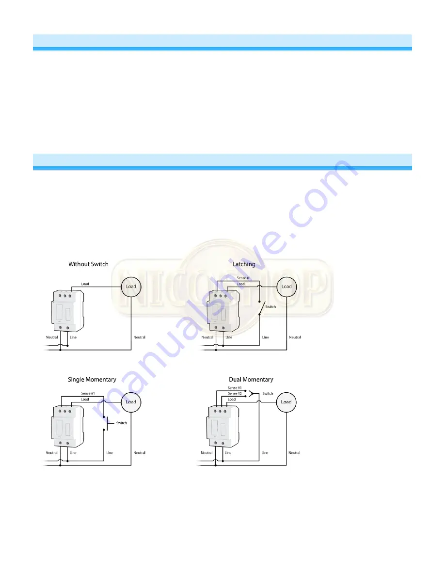
7)  Connect wires per diagram which corresponds to your installation 
Note: sense lines carry very low current (~0.35mA 240V, ~0.17mA for 120V)


8)  After ensuring wires are firmly connected and that there is no exposed wire, turn on breaker/fuse 

After a few seconds, load will turn on and DIN Rail LED will turn green 

9)  Test by tapping DIN Rail paddle top and bottom 

Load will turn on and off 
DIN Rail LED will turn green when load is on and red when load is off 

Summary of Contents for 2453-222

Page 1: ...Page 1 of 16 2453 222 2453 422 2453 522 Rev 1 21 2014 7 51 AM DIN Rail On Off Owner s Manual 2453 222 US 2453 422 EU 2453 522 AUS NZ...

Page 2: ...s 6 Change LED Brightness 6 Error Blink 7 INSTEON Setup 7 INSTEON Controllers Responders and Links 7 Make DIN Rail a Responder 7 Make DIN Rail a Controller 7 Groups 8 Scenes 8 Make DIN Rail a Controll...

Page 3: ...pecified maximum s or install in locations with electricity specifications which are outside of the product s specifications If this device supports dimming please note that dimming an inductive load...

Page 4: ...off breaker fuse and verify power is off 2 Disconnect wires from light fixture Strip away wire coating until you have 5 16 8mm of bare wire on the ends 3 After ensuring the wires are not touching tur...

Page 5: ...y 3 Way Toggle Mode Latching Switches Only Default Because DIN Rail module comes programmed for latching switches 3 way toggle mode is enabled by default Normally a latching switch reads the switch s...

Page 6: ...Single Momentary Wall Switch Dual Momentary Wall Switch Adjust Local Settings Change LED Brightness DIN Rail s LED is set at a default 50 brightness but it can be set anywhere from off to 100 brightn...

Page 7: ...nders only e g FanLinc and some can be controllers and responders e g switches and dimmers The association between the controller and responder is called a link Note that a link is one way If you want...

Page 8: ...ng device A is now a controller of device B 4 Press and hold device B set button until it beeps Device B LED will start blinking green 5 Press and hold device A set button until it double beeps Device...

Page 9: ...on until it beeps Controller LED will start blinking green 2 Press and hold controller button until it beeps a second time Controller LED will start blinking red 3 Press and hold DIN Rail set button u...

Page 10: ...beep and its LED will stop blinking 3 Test by sending X10 on and off commands Load will turn on and off Remove X10 Address 1 Press and hold DIN Rail set button until it beeps DIN Rail LED will start b...

Page 11: ...ct beacon Yes INSTEON device category 0x02 Switched Lighting Control all frequencies INSTEON device subcategory US 0x2E EU 0x33 AUS NZ 0x34 X10 X10 address 1 optional comes unassigned X10 transmitter...

Page 12: ...mum load None User replaceable fuse US 16A 5x20mm slow blow burn glass fuse EU No user replaceable fuse AUS NZ Hardwired remote control Yes either latching or momentary switches supported Retains all...

Page 13: ...ot using DIN Rail in X10 mode DIN Rail may have an undesired responder membership Use software to remove membership or perform a factory reset DIN Rail responds to on commands but not off commands Loa...

Page 14: ...ice provides a phase bridge to DIN Rail module If the other dual band device is blinking red it is on the same phase Device does not provide a phase bridge to DIN Rail module Relocate if necessary and...

Page 15: ...ires that the equipment bearing this symbol on the product and or its packaging must not be disposed of with unsorted municipal waste The symbol indicates that this product should be disposed of separ...

Page 16: ...or electrical or mechanical tampering For optimal use manually verify the device state Any home automation device should be viewed as a convenience but not as a sole method for controlling your home...

Reviews: