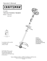
background image

Summary of Contents for 104.79211

Page 1: ...istance with assembly or operation call 1 800 235 5878 SAFETY ASSEMBLY OPERATION MAINTENANCE TROUBLESHOOTING WARRANTY CAUTION Before using this product read this manual and follow all safety rules and operating instructions Sears Roebuck and Co Hoffman Estates IL 60179 U S A Visit our web site www sears com craftsman 769 03546 ...

Page 2: ...nstructed equipped and maintained for the prevention of fire Check with with your state or local authorities for regulations pertaining to these requirements Failure to follow these require ments could subject you to liability or a fine This unit is is factory equipped with a spark arrestor All information illustrations and specifications in this manual are based on the latest production informati...

Page 3: ... engine exhaust from this product contains chemicals known to the state of California to cause cancer birth defects or other reproductive harm Do not operate the engine faster than the speed needed to cut trim or edge Do not run the engine at high speed when not cutting Always stop the engine when cutting is delayed or when walking from one cutting location to another If you strike or become entan...

Page 4: ...50 KEEP BYSTANDERS AWAY WARNING Keep all bystanders especially children and pets at least 50 feet 15 m from the operating area OIL Refer to operator s manua for the proper type of 0i THROWN OBJECTS AND ROTATING CUTTER CAN CAUSE SEVERE INJURY WARNING Do not operate without the cutting attachment shield in place Keep away from the rotating cutting attachment DO not tOUC h a hot muffler gear housing ...

Page 5: ...parts CuttingAttachment Shield Fig 2 FOR STRAIGHT SHAFT TRIMMERS Place the cutting attachment shield onto the shaft mount Install using provided hardware in the sequence as shown Fig 3 Ji Shaft Mount I I I I i Cutting Attachment Shield Plate Washer _ _ Washer _ Lock Washer Attachin Screws Fig 3 INSTALLING THE UPPER HANDLE AND SAFETY BAR 1 Locate the 4 screws included in the tool kit 2 Assemble the...

Page 6: ...il and remove the paper seal covering the opening Replace the top Fig 5 2 Place the unit on a level surface Fig 6 Fig 6 3 Remove the oil plug dipstick from the crankcase Fig 7 4 Pour the entire bottle ofoil into the oil fill hole Fig 7 4 Cycle Motor Oil Fig 5 NOTE Save the bottle of oil It can be used to measure the correct amount during future oil changes See Changing The Oil p 13 Oil fill plug d...

Page 7: ...ty up to 500 000 and 5 years imprisonment 49 U S C 5124 6 Never put in luggage or take on trains or aircraft 7 To discard contact local refuse hauler or recycle center Never put in fire or incinerator Do not puncture If your cylinder was purchased with a Green Key _ or similar device install it when empty and cylinder may be recycled with other steel items NOTE FIRE EXPLOSION HAZARD Contains enoug...

Page 8: ... slight momentary leak of propane as the connector is being screwed in Make sure that the connector is installed tight enough that any leakage stops Hand tight is sufficient Slide canister back so all of fuel line components are behind the guard and latch the canister clamp Fig 9A Propane Connector Fig 9B REMOVING THE PROPANE CANISTER I Make sure the engine is off 2 Un latch the bottle clamp and p...

Page 9: ...curely tighten the knob before operating this unit Except for edging attachments are to be used in the receiving hole only Using the wrong hole could lead to personal injury or damage to the unit Always install the attachment so that the engine is upright propane tank on bottom when unit is oper ated A secondary receiving hole is provided for use of a trimmer being used for edging only No other ac...

Page 10: ...p for 30 to 60 seconds NOTE This unit is provided with a Fast Idle Lock Fig 14 If experiencing starting difficulties under regular conditions squeeze the throttle control then push and hold the Fast Idle lock forward while releasing the throttle trigger Then start the unit Stop Off Start On I Fast Idle Lock Safety trigger Throttle Control Fig 14 NOTE When starting the engine in very hot or cold co...

Page 11: ...th foreign matter Normal line fatigue Attempting to cut thick stalky weeds Forcing the line into objects such as walls or fence posts NOTE This unit is equipped with an Anti Kickback bar This bar helps protect you from kick back which may occur during operation The Anti Kickback bar hits the side of your leg when the trimmer jumps back prevent ing the cutting head to contact the operator Fig 15 TI...

Page 12: ...case cannot be overemphasized Check oil before each use 1 Stop the engine and allow to cool 2 Place the unit on a fiat level surface to get a proper oil level reading 3 Keep dirt grass clippings and other debris out of the engine Clean the area around the oil fill plug dipstick before removing it 4 Remove the oil fill plug dipstick and wipe offoil Rein sert it all the way back in S Remove the oil ...

Page 13: ...he unit and clean up any oil that may have spilled Dispose of the oil according to Federal State and local regulations 5 Refill the crankcase with 2 5 fluid oz 75 mL of SAE 10W 30 SF SG or SH oil NOTE Use the bottle saved from initial use to measure the correct amount of oil The bottle measures approximately 2 5 fluid oz 75 mL Fig 16 Check the level with the dipstick If the level is low add a smal...

Page 14: ...dle speed screw counterclockwise 1 8 of a turn at a time as needed to reduce idle speed Checking the fuel cleaning the air filter and adjusting the idle speed should solve most engine problems If not and all of the following are true check the spark plug for proper gap and condition the engine will not idle the engine hesitates or stalls on acceleration there is a loss of engine power If problem s...

Page 15: ...en replacing line 1 Insert both ends of your line into the insertion holes in the side of the cutting head Fig 23 3 Pull the ends of the line until the line bend is centered between the two insertion holes and firmly against the side of the cutting head Fig 25 Fig 25 4 Correctly installed line will be the same length on both sides Trimming Line Insertion Holes Positioning Tunnel _ Glide Plate Fig ...

Page 16: ... feeler gauge and accidentally depress the valve and valve return spring Measure both the intake and exhaust valve distances Adjusting Screws Rocker Arm Jam Nuts Feeler Gauge Engine cover screws _ Z Engine cover screws Fig 26 5 Clean dirt from around the rocker arm cover 6 Remove the three screws holding the rocker arm cover with a phillips head screwdriver 7 Remove the rocker arm cover and gasket...

Page 17: ...k plug and drain all of the oil from the cylinder before attempting to start the trimmer after storage 3 Change the oil referring to Changing the Oil p 13 Dispose of the old oil in accordance to Federal State and Local regulations 4 Thoroughly clean the unit and inspect for any loose or damaged parts Repair or replace damaged parts and tighten loose screws nuts or bolts The unit is ready for stora...

Page 18: ...TION STARTER PULL START WITH AUTO REWIND MUFFLER BAFFLED wITH GUARD THROTTLE SAFETY LOCK WITH MANUAL SPRING RETURN DRIVE SHAFT AND HOUSING DRIVE SHAFT HOUSING ALUMINUM TUBE THROTTLE CONTROL FINGER TIP TRIGGER APPROXIMATE UNIT WEIGHT 13 1 14 9 LBS C UTTING MEcHANISM HASs REE _ CuTTING H EAD CUTTING HEAD DIAMETER 4 1 4 INCHES 108 mm TRIMMING LINE RED MEDIUM 71 85908 OR BLACK LARGE 71 85909 CUTTING P...

Page 19: ...tection Agreement can save you money and aggravation Here s what the Repair Protection Agreement includes Expert service by our 10 000 professional repair specialists Unlimited service and no charge for parts and labor on all covered repairs Product replacement up to 1500 if your covered product can t be fixed Discount of 10 from regular price of service and related installed parts not covered by ...

Page 20: ...Our Home For repair of carry in items like vacuums lawn equipment and electronics call anytime for the location of your nearest Sears Parts Repair Service Center 1 800 488 1222 U S A www sears com 1 800 469 4663 Canada www sears ca To purchase a protection agreement on a product serviced by Sears 1 800 827 6655 U S A 1 800 361 6665 Canada Para pedir servicio de reparaci6n a domicilio y para ordena...

Reviews: