background image

28

 Notices for using Inspur driver U disk to load driving under windows system 

During the installation of Windows operating system, if the driver of hard disk 

controller is loaded by using Inspur driver U disk, entering the interface of disk 
partition, the Inspur driver U disk will occupy a disk characteristic. If the disk is not 
divided, U disk will occupy disk C: and if the disk has other partitions, U disk will 
occupy other disk characteristics (please distinguish according to the actual hard disk 
partition).

If there are other partitions on the disk, at this moment, it needs to delete all of 

them and then create new partitions on the hard disk, and the U disk will not occupy 
disk characteristics any more.

If the disk is not divided, it needs to create one disk partition on the unallocated 

space, then delete this newly created disk partition, and at this time the U disk will not 
occupy any disk characteristic any more. Then create disk partition based on actual 
need, and complete the installation of operating system according to the instructions.

Notes: Be sure to distinguish between U disk and hard disk, never delete or format 

U disk.

5.2 Manually Install Windows Server 2003 Enterprise Edition

5.2 Manually Install Windows Server 2003 Enterprise Edition

5.2.1 Preparation Prior to Installation

5.2.1 Preparation Prior to Installation

 Installation CD for Windows Server 2003 Enterprise Edition (support 32 bit or 

EMT 64 bit versions).

 Inspur system driver CD.

 Driving 

fl

 oppy for 8708 SAS RAID card (make by using driver CD for Inspur 

RAID card, for details, refer to the electronic version of  User Manual in the driver CD 
for RAID card).

 Windows Server 2003 Service Pack 2 (it needs to be prepared by yourself; if 

you use the installation CD of integrated SP2 version, it does not need to install the 

Chapter Five Installation of the Operating system

Chapter Five Installation of the Operating system

Summary of Contents for Yingxin NF5280M2

Page 1: ...ecting the envi ronment This manual is property of Inspur Group Co Ltd The User Manual is not to be copied by any group or individual in any manner without the consent of Inspur Group Co Ltd Inspur Group Co Ltd reserves the right of revising this manual momentarily The contents of this manual are subject to changes without further no tice Feel free to contact Inspur Group Co Ltd if you have any qu...

Page 2: ...omponents in the case by yourself 3 In this server the MEMORY CPU CPU Fan and Fan are in given standard Please don t mix them with the components of other servers 4 When you have any software problem during the application of this server please contact the corresponding software supplier who would then communicate with us Good communication shall help us solve your problem in a timely manner This ...

Page 3: ...erred in this manual are property of the corresponding companies 9 In the above statement we indicates Inspur Group Co Ltd Inspur Group Co Ltd holds the right of final explanation about the above statement ...

Page 4: ...r Five Operating System Installation Chapter Five Operating System Installation In this chapter how to install the main operating system to this server is intro duced Chapter Six Common Problems and Trouble shooting Chapter Six Common Problems and Trouble shooting In this chapter solutions to some common problems are introduced Chapter Seven Instructions of baseboard management controller Chapter ...

Page 5: ...tallation Chapter Five Operating System Installation 23 23 5 1 Application Instructions for Inspur Drive U Disk 24 5 2 Manually Install Windows Server 2003 Enterprise Edition 28 5 3 Manually install Windows Server 2008 Enterprise Edition 34 5 4 Manually install Red Hat Enterprise Linux 5 2 37 Chapter Six Common Problems and Trouble shooting Chapter Six Common Problems and Trouble shooting 41 41 6 ...

Page 6: ...ent Chip BMC IP 47 7 2 Remote Login 47 7 3 Function Menu Introduction 48 Chapter Eight Server Installation Guide Chapter Eight Server Installation Guide 54 54 8 1 Cabinet preparation 54 8 2 Components needed by server installation 55 8 3 Installation of inner rail 55 8 4 Install guide rail into cabinet 56 8 5 Install the server to cabinet 58 ...

Page 7: ... ratings of the extended cables to make sure that the sum of rated current of all products inserted into the extended cables make sure that the sum of rated current of all products inserted into the extended cables do not exceed 80 of the limits of the rated currents of the extended cables do not exceed 80 of the limits of the rated currents of the extended cables Warning 4 Please be sure to use t...

Page 8: ...please contact the local waste recovery and treatment mecha nism nism If what you bought is the chassis besides carefully read the installation descrip tion attached with the cabinet products and get known about the special warning no tices and installation process you must abide by the following preventive measures to guarantee the cabinet to be stable and safe Warning 10 Before installing equipm...

Page 9: ... the power socket wait for 10 to 20 minutes and then open the cover of the host Move the equipment to the ventilation place to dry the system at least for 24 hours and make sure that the system is fully dried Close the cover of the host re connect the system to the power socket and then start the equipment In case of operation failure or abnormal situation please contact Inspur and get technical s...

Page 10: ...ease do not take them out from the antistatic package materials During the work please touch the earthing conductor or the unpainted metal sur face on the cabinet regularly to conduct off the static electricity on the body that may damage the internal components 7 When dismounting the internal components with the approval of Inspur please pay attention to the following matters Switch off the syste...

Page 11: ...o the sequences from the bottom to the top and first install the heaviest component When pulling out the components from the cabinet it shall apply force slightly to ensure the cabinet to keep balance and stabilization When pressing down the release latch of the sliding rail of components and slid ing in or out please be careful as the sliding rail may hurt your figures Never make the AC power bra...

Page 12: ...r serial interface Network Interface Two gigabit Network card interfaces and one management interface Display Interface One VGA interface UID interface One UID blue and UID button Display controller Display controller Controller type Main board integrated AST2050 display controller Video Memory 8MB video memory SAS Back board SAS Back board SAS2 0 back board Applicable to hot plug SAS SATA hard di...

Page 13: ... disk Hard disk Hard disk type 3 5 inches SAS and SATA hard disk 2 5 inches SAS and SATA hard disk External memory driver External memory driver CD ROM Slim SATA DVD CD ROM the server with 17 24 hard disks of 2 5 inches type can not collocate Slim CD ROM Driver U disk Optional to driver U disk Power Power Specification 600 W single supply or above 550W and 1 1 redundancy Power input Please refer t...

Page 14: ...l system indicator light It warns the abnormal status of the system such as over high temperature amber This light is always off when the system works normally But the light is also on when the server is connected with AC and BMC is initialized D Network card 1st and 2nd indicator light On network is connected green Off network is not connected E Reset button System reset button F Power button Ser...

Page 15: ...uilt 2 2 2 2 5 Inches Hard Disk Configuration Front Panel View 8 Hard Disks Front Panel View 16 Hard Disks Front Panel View 24 Hard Disks Front Panel View Serial number Name Specification 1 Front USB interface To connect the USB devices 2 Hard disk bay To install the 1st 8th hard disk 3 Hard disk bay To install the 9th 16th hard disk 4 Hard disk bay To install the 17th 24th hard disk 5 CD ROM slot...

Page 16: ...ator light Green flashing network is being connected and data are being transmitted Light off network is disconnected 6 ID light User machine locating light blue 7 Fan failure indicator light It warns fan failure This light is always off when the system is in normal status The light is always amber in case of system fan failure The light is also amber when server is turned off AC power is connecte...

Page 17: ...ew iew Number Name Function and specification 1 Power input interface For connecting power line the above picture shows double power configuration model 2 Serial interface For connecting serial interface devices 3 VGA interface For connecting display devices 4 Management interface For the usage of main board integrated IPMI management function 5 Rear USB interface For connecting USB interface devi...

Page 18: ...ding origi nal setup Hence when there are operating problems in the system due to the alteration the setup can be reversed 2 The factory default system value is usually the optimized setup Don t try to al ter the parameters before you understand their denotations 3 The common setup is introduced in detail in this paper The less referred op tions in the application procedure are explained simply or...

Page 19: ...ey introduction Operation key introduction Key Description for selecting the upper menu or value for selecting the next menu or value for selecting the left menu or value for selecting the right menu or value ESC for returning to the superior menu or the main menu for changing the item value for changing the current menu item into the previous item value The key only displays the item values relev...

Page 20: ...play the detailed information installed in the system including manufacturer CPU frequency front end bus the size of cache and so on SATA Configuration The options in this menu can be used to set integrated motherboard SATA control ler functions and IDE devices SATA Configuration In SATA channel mode setting there are three options Disabled Enhanced and Compatible If you don t use RAID when using ...

Page 21: ...ss Set to Disabled it will show the self test process and test information set to Enabled de fault it will display the LOGO of manufacturers Boot Device Priority Enter this menu and select certain boot order device item Press Enter button and the system will display optional boot device table Then select a device through ar row key in the table to finish the setting of the boot order item Note If ...

Page 22: ...wer off Its default setting is Power Off the state of off which needs manual boot for availability Power On is the state of on Last State is the state before power off VI Exit menu VI Exit menu The options in Exit menu can be used to save or discard the settings of the changes in the BIOS and exit the setting program Save Changes and Exit Select this item and press Enter After select OK for confir...

Page 23: ...y pressing F8 3 2 Motherboard Jumper Settings 3 2 Motherboard Jumper Settings Motherboard jumper setting is the operation of shorting out two pins of the jump er to change the interface functions Refer to the following figure and adjust the moth erboard functions Jumper Setting View Jumper Setting View Open the Case Upper Panel Open the Case Upper Panel If the operation hereafter is needed please ...

Page 24: ...er Location View Jumper Number Function description Jumper function CLR_CMOS CMOS clearing jumper Normal state short cut the pin 1 and 2 Clean CMOS short cut the pin 2 and 3 Note When clearing CMOS the system must be shut down and cut off the power sup ply Short cutting pin 2 and 3 need to keep for 5 seconds then use the jumper cap to short cut pin 1 and 2 default settings of the CLR_CMOS to resto...

Page 25: ...ration interface of SATA HostRAID 4 2 Application of Control Keys 4 2 Application of Control Keys Press key Description Move the cursor in different menus or change the options of menu TAB Select the next menu configuration item Enter Select menu Esc Exit the menu or return to the last menu from the submenu 4 3 Setup of SATA HostRAID 4 3 Setup of SATA HostRAID After entering into the configuration...

Page 26: ... I Create RAID Volume After entering the configuration interface of SATA HostRAID it can select the menu with up and down arrow keys and then press Enter key to create RAID volume menu The system will display the following menu options Name Please input the volume name of less than 16 characters without special characters RAID Level Please select RAID volume grade if it has not created volume at p...

Page 27: ...ync Set synchronous mode and if it is to select to create Recovery it needs to set this option Alter all the setting above have been done well please select Create Volume and press Enter the screen will display WARNING ALL DATA ON THE SELECTED DISKS WILL BE LOST Are you sure you want to create this volumes Y N If the creation of RAID volume is confirmed please enter Y the volume will then be creat...

Page 28: ... hard disk will be lost and at the same time the hard disk will never again belong to RAID volume IV Recovery Volume Options menu IV Recovery Volume Options menu After entering the configuration interface of SATA HostRAID it can select the menu by the up and down arrows and then press Enter key to enter the menu Notes only after creating the Recovery volume can it perform the operation to the menu...

Page 29: ...directory in Inspur system driver CD for the mak ing method of the driver floppy disk If the system you purchased is configured with Inspur drive U disk you may refer to relevant contents of this chapter for the making method of Inspur drive U disk If your server is configured with external RAID card or SAS sub card please refer to the electronic version of User Manual in the CD for the external R...

Page 30: ... disk after reboot it must enter the server BIOS for setting to ensure the starting sequence of hard disk is prior to the starting sequence of U disk and the system can be booted from the disk If the starting sequence of U disk is prior to the starting sequence of hard disk the system will fail to be booted from hard disk The following introduces the making method for the driver of controller of m...

Page 31: ...t driver be guaranteed 2 Put the driver CD Inspur system driver CD and RAID card driver CD into the CD driver and the driver making software will operate automatically If the system forbids the automatic operation of CD please enter CD contents and operate documents of dolphin bat Inspur system driver CD in CD or setup exe RAID car driver CD in CD contents 3 Methods for making drivers by using Ins...

Page 32: ...ton and exit the logging 2 After entering the navigation code and logging enter the main interface of driver making software and the main interface is as the following picture 3 Click the Make Drive button and enter the driver making interface as shown in the following picture Chapter Five Installation of the Operating system Chapter Five Installation of the Operating system ...

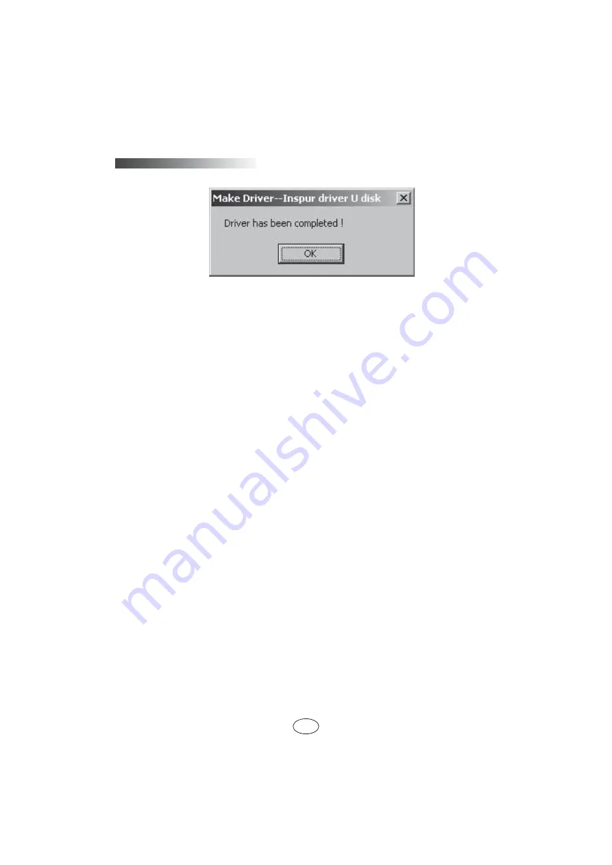
Page 33: ...ctly into the analog driver A of Inspur driving U disk Select the Windows version to be installed and driver to be made and then click Next The system will display a warning as shown in the following picture Please confirm that Inspur driving U disk is well connected and format the floppy A of Inspur driving U disk and then click OK to start the driver making After the driver fabrication completed...

Page 34: ...d at this time the U disk will not occupy any disk characteristic any more Then create disk partition based on actual need and complete the installation of operating system according to the instructions Notes Be sure to distinguish between U disk and hard disk never delete or format U disk 5 2 Manually Install Windows Server 2003 Enterprise Edition 5 2 Manually Install Windows Server 2003 Enterpri...

Page 35: ...o the controller and press Enter to continue After the driver is loaded press Enter key to continue the installation according to the screen prompts 4 The system displays Welcome to Setup the installation program of this part prepares to operate Microsoft R Windows R on your computer To set up Windows now press ENTER To repair a Windows installation using Recovery Console press R To quit Setup wit...

Page 36: ...le system Format the partition using the FAT file system Select format the partition using the NTFS file system it is suggested to use and press Enter to format the disk partition 10 Select format the partition using the NTFS file system it is suggested to use and press Enter to format the disk partition After the installation program formats the new partitions it will promote Please wait while Se...

Page 37: ...n Client Access License The user can select and set according to his needs and then click Next 16 Computer Name and Administrator Password After setting the name can not exceed 15 characters and password can not exceed 14 characters of computer based on the actual situation click Next to continue the installation 17 Date and Time Settings After setting the correct date and time click Next to conti...

Page 38: ...on 6 Enter the interface of License Agreement and select Yes to continue the installation 7 Enter the interface of Readme File Information and click Next to continue the installation 8 The program starts to install and click Next according to the prompt 9 When the installation completes click Finish according to the prompt take out the driving CD and restart the system 23 Install Network card driv...

Page 39: ...not this time and click Next 5 The window Hardware Update Wizard will be shown select Install from a list or specific location Advanced and click to continue 6 Insert Inspur system driver CD into the CD ROM select Search for the best driver in these locations then select Include this location in the search and then select the path of the driver in the CD driver video nf5280m2 win03_32 and click OK...

Page 40: ...ect and set the language and other options according to the actual need and click Next to continue 4 Click Install now to continue with the installation confirmation interface Then select the operating system to be installed and click Next to continue 5 Input your product key 25 characters and then click Next to continue 6 The Microsoft software license clauses will be shown in the interface of Pl...

Page 41: ... interface of The user s password must be changed before logging on for the first time Take out the installation CD ROM and driver U disk and then click OK to continue 12 Follow the prompt to set the administrator password and then click the arrow button at the right of the password input box to continue If the password meets the requirements it will prompt Your password has been changed and then ...

Page 42: ...nterface popped out after the disk s running and input the navigation code on the driver CD case in the navigation code verification interface popped out after the operation of CD and click OK to enter the installation interface automatically 2 In the Select OS column select Windows 2008 3 In the Select Hardware column select Network card driver Select 32bit or 64bit driver according to the instal...

Page 43: ... computer click Next 8 After the driver is finished installation click Close in the window Windows has successfully updated your driver software according to the prompts 9 Click Yes according to prompt and take out the driver CD and restart the machine 17 After the system is restarted it completes the installation of Windows Server 2008 5 4 Manually install Red Hat Enterprise Linux 5 2 5 4 Manuall...

Page 44: ...nstallation shall take the customizing manual partitioning as an example please select Create Custom layout and click Next to continue the installation 9 When the installation program enters into partition creating interface if partition has been created on the hard disk it will be showed and you can delete it if you do not need it select the disk and then click New to create new partition 1 Selec...

Page 45: ... the installation CD and driver floppy then the system would reboot automatically 17 The system reboots to enter into Welcome interface click Forward to continue the installation 18 The installation program enters into License Agreement interface select Yes I agree to the License Agreement and click Forward to continue the installation 19 The installation program enters into Firewall interface sel...

Page 46: ...ns and the Terminal menu in Accessories and input the following in the windows mount dev cdrom mnt Enter cd mnt Enter cd driver nic linux 5280m2 Enter cp igb 1 3 8 6 tar gz tmp Enter cd tmp Enter tar zxvf igb 1 3 8 6 tar gz Enter cd igb 1 3 8 6 src Enter make install Enter reboot Enter Notes igb 1 3 8 6 tar gz is network card driver and its version will be updated When being installed the actual v...

Page 47: ... and restart the operating system Ctrl Alt Del Clear up system RAM self check the POST again and restart the operating system Reset button Cold boot again switch off and restart the system power so that to clear up the system RAM to self check the POST again to restart the operating system and to power up all peripherals again Power button 6 2 Problems when starting the machine 6 2 Problems when s...

Page 48: ...ou may pull and plug RAM and clear CMOS for test 6 2 3 Installation system can t find hard disk 6 2 3 Installation system can t find hard disk 1 When install the system directly booted with the system CD if it prompts that no hard disk can be found please check the normality of the disk state and power on self check hard disk state 2 If the power on self check can detect the hard disk but the hard...

Page 49: ...or restart For blue screen restart or halt of the machine in the utilization of the system you may resort to the following measures 1 If other external non Inspur component or some application program software is installed before the fault it is suggested to remove it and go on to test your server 2 Use the latest antivirus software for antivirus test 3 It is suggested that you record the displaye...

Page 50: ...n then it is likely that the RAID card has set off the alarm There may be array abnormality When the hard disk back plate alarms there is always abnormal status lamp of the hard disk on the front panel which can be used to our advantage 3 After having collected the basic information please feedback the detailed alarm information to Inspur technical support personnel in a timely manner We will make...

Page 51: ...3 4 Losing the machine attached Ruijie server suite and System Driver program CD 6 3 4 Losing the machine attached Ruijie server suite and System Driver program CD Please visit the Inspur s official website and download the correct version corresponding with your machine model 1 Download Ruijie server kit from http www inspur com downloads channel_home Downloads_sv_1 asp 2 Download Inspur system D...

Page 52: ...rver please take the following measures 1 If you have doubt in product configuration and specification details please contact your supplier 2 If there is system problem in using the machine please contact the customer service center of Inspur server directly please record the product serial number on your host case After receiving your service request our technical support personnel will provide y...

Page 53: ... 2 1 Remote client system requirements The requirements of remote client system of GUI interface connecting to the server management chip through web browser are shown in the following table Purpose Operational approach Operation system Support the operation system of Microsoft Internet Explorer browser Windows XP is recommended Browser plug in module Install Java SE Runtime Environment 6 Updata 1...

Page 54: ...f the interface System Information Server Health Configuration Remote Control Maintenance and Languages 7 3 1 System Information Menu 7 3 1 System Information Menu In the menu the power supply status and Firmware information of management chip can be seen 7 3 2 Server Health Menu 7 3 2 Server Health Menu In the menu data information relating to server health including sensor readings temperature v...

Page 55: ...ee kinds Administrator Operator and NO Access Administrator can conduct all operations Operator only can perform general application operations and can t change configuration and update Firmware NO Access not allowed to log in remote management interface 6 BMC Sensor Setup BMC SensorAdress or change mode 7 Date Time NTP Settings configure the Date time and NTP Server 7 3 4 Remote Control Menu 7 3 ...

Page 56: ...tall well browser plug in module before logging in remote desktop Start using all options relating to Active X in Internet local Intranet and trusting sites in the option of tool Internet option safety In the option of tool Internet option advanced option don t tick the option of don t store the cryptographic page in the hard disk and save A Remote desktop Video set A Remote desktop Video set Chap...

Page 57: ... option equal to click the Ctrl key of the left side when operating Hold Left Alt Key Select this option equal to click the Alt key of the left side when operating Left Windows Key Select this option will appear Hold down and Press and Release Stands for press down or release Windows key of the left side Right Windows Key Select this option will appear Hold down and Press and Release Stands for pr...

Page 58: ...Option menu Bandwidth and Video Settings will appear Bandwidth is used to set transmission bandwidth Video Setting is used to set transmission picture quality and transmission efficiency E Remote desktop Device set E Remote desktop Device set Options Options Redirect CDROM Synchronize with CDROM of client Redirect ISO Synchronize with image of client Redirect Floppy USB Synchronize with floppy dri...

Page 59: ...d appear drop down menu Languages select corresponding language a soft keyboard frame will appear 7 3 5 Maintenance menu 7 3 5 Maintenance menu It can realize remote updating of BMC firmware We recommend users not to refresh it by themselves if it really needs to be refreshed the refresh file must have been approved by us 7 3 6 Languages menu 7 3 6 Languages menu It is used to select languages of ...

Page 60: ...abinet door for convenience of guide rail installation Cabinet grounding To avoid electric shock a grounding device must be installed in the cabinet If the server power line is installed in the power socket which constitutes a portion of the cabinet grounding should be properly provided for the cabinet If the server power line is inserted into the power socket in the wall the grounding device in t...

Page 61: ...e install the inner rail to the cabinet according to the following description 1 Firstly take out the inner rail from the guide rail hold the front fixed frame of the whole guide rail and pull outward the inner rail just as shown in picture 2 Picture 2 2 When the inner rail can t be pulled any more stir the bayonet lock shown in picture 3 along the direction of arrow and then pull outward the inne...

Page 62: ...n push the inner rail again After the inner rail is clamped tightly screw down and then push the inner rail again After the inner rail is clamped tightly screw down Picture 5 5 Repeat step 1 4 install the other inner rail in the corresponding position at the other side of the cabinet 8 4 Install guide rail into cabinet 8 4 Install guide rail into cabinet 1 Make sure the installation location of th...

Page 63: ...picture 7 fix well the second hole picture 6 on the front and back frame corresponding to angle rail Picture 7 3 Repeat the above operation install the other guide rail to the cabinet Chapter Eight Server Installation Guide Chapter Eight Server Installation Guide ...

Page 64: ...ull forward the bayonet lock at the front of the inner rail at the same time push it into the cabinet Picture 8 4 Use fixed screw picture 7 to fix the server to the cabinet through the third hole picture 9 in the front of guide rail corresponding to angle rail Special notice if the third hole screw is accompanied with the cabinet front panel Special notice if the third hole screw is accompanied wi...

Reviews: