D
IGITAL
M
IXING
I
N
L
IVE
S
OUND
4-27
User Guide - © InnovaSON - January 2004
4.D MIX BUSSES
Following the same procedure you have previously seen concerning the assignment of faders to
inputs, we’ll now find out how to allocate faders to mix busses. We will then look at the gateway that
allows you to link inputs and outputs:
“The Routing”
.
4.D.1 DSP Resources : some important points
The mix busses are created in real time by the digital signal processing housed in the Mix Box DSP
module. You will have seen on the previous pages of this section (paragraph 4.C.2.3) that when a
fader nominated an as Input is patched to a physical input, it uses a DSP resource out of the 80 (or
48) initially available resources. Once this resource has been used, it remains there for all other pages
of the current file, to optimize the latency when page changing. It's the same for the DSP resources
concerned with the mix busses. You will see that, as with the PATCH IN grid, the PATCH OUT grid
contains a DSP resource allocation line.
4.D.1.1
Mix resources
The DSP Sy80 module is programmed to provide 48 mixing resources (DSP Sy40-8 provides 26).
These resources give rise to busses, which are distributed to the various outputs channels of the local
audio rack (Mix Box).
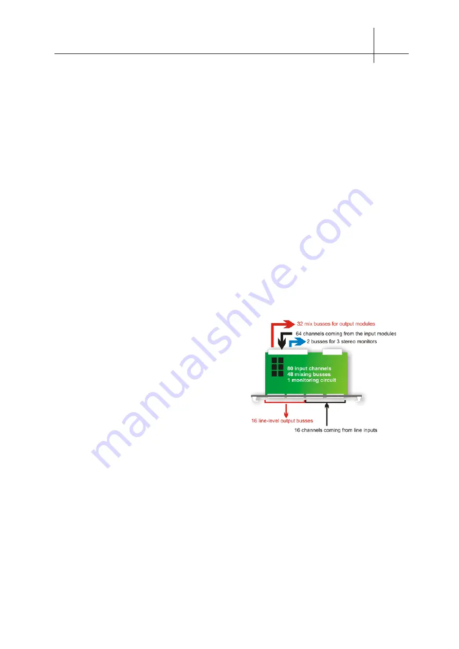
Mix Box can handle up to 96 audio channels. Each
channel represents a stream of digital audio words, with
24-bit resolution and a 48KHz sampling frequency.
64
of
these channels are used for the bi-directional exchange
of information between Mix Box and Stage Box, via the
coaxial cable.
32
channels are reserved for mix busses
created by the DSP module.
These
32
channels are
only available in Mix Box, because they are not
transmitted on the coaxial cable
. Up to
32
resources of
DSP mixing can thus feed the outputs of the modules
present in Mix Box.
The
16
remaining resources can feed Line Outputs, available on the DSP Sy80 module’s SUB-D25
connectors; these resources can be also used in local busses for the creation of Subgroups. These
busses patched on line outputs are accessed by the DSP module only and the corresponding signals
are not displayed on the screen but only on the console’s bar-graphs.
Finally,
2
DSP resources, which in fact makes the total 50 for Sy80 (and 28 for Sy40) are dedicated to
the function of stereo monitoring, and cannot therefore be used for anything else.
The schematic below shows the architecture used for the Sy80’s DSP programming.
Summary of Contents for SY40
Page 2: ......
Page 12: ......
Page 38: ......
Page 58: ......
Page 106: ......
Page 128: ......
Page 146: ......
Page 169: ......
Page 187: ......
Page 215: ......
Page 221: ...TECHNICAL CHARACTERISTICS RACKS AND MODULES 9 15BIS User Guide InnovaSON April 2005 ...
Page 226: ...TECHNICAL CHARACTERISTICS RACKS AND MODULES 9 19 User Guide InnovaSON January 2004 ...


