background image

3-12


S

ENSOFT

8.1

User Guide -  © InnovaSON - January 2004 

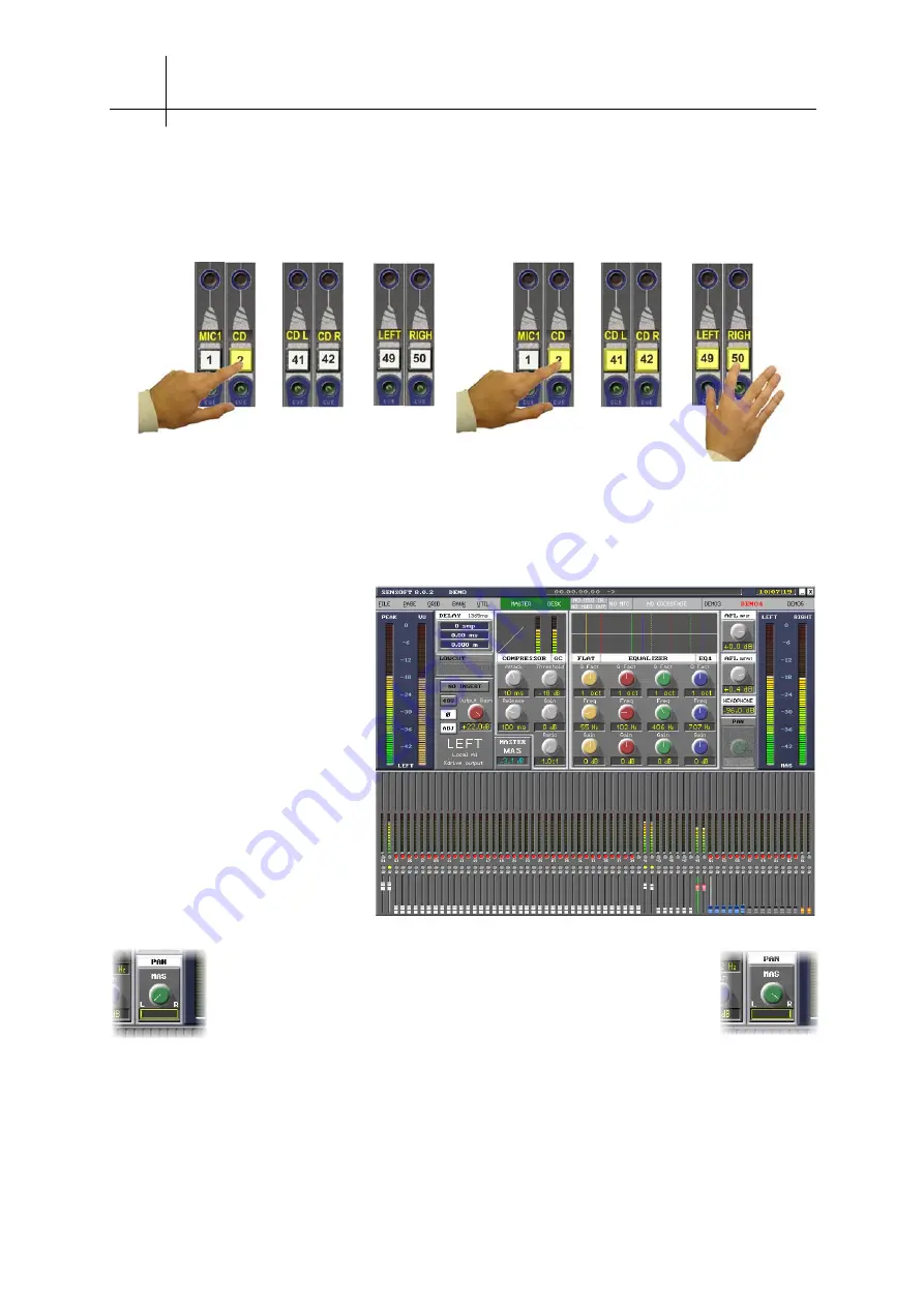
Return to the main Mix window (by pressing the [ESC] key on the keyboard, or by pressing the 
[

PATCH IN

] button on the console again) to route the “CD” channel to the Master busses. 

As long as the CD player is 
outputting music, you will find that 
the “CD” channel (fader 2) acts as a 
VCA for both inputs “CD L” and “CD 
R”. In fact, looking beyond this 
channel, you can assimilate a bank 
of inputs, providing much more than 
simple VCA control. Note that it is 
always possible to adjust the 
balance of both “CD L” and “CD R” 
inputs by acting directly on their
X

FAD

 when the “CD” channel is 

spread.

Now let’s assign the “CD L” and “CD R” inputs to the left and right 
Master busses respectively, using the pan settings. Select X

FAD

 “CD L” 

(if necessary, “spread” this by first selecting the “CD” channel) and, by 
means of the console’s rotary [

PAN

] control, pan the signal totally to 

the left. Repeat the operation for X

FAD

 “CD R”, to pan it to the right. 


Routing the “CD” channel to the Master bus automatically routes the (X

FAD

) channels “CD L” and “CD R”

managed by this channel 

Summary of Contents for SY40

Page 1: ...Sensoft 8 1 full Sensoft 9 installation Sensoft 9 Addendum updates sections 3 and 4 of this user guide User Guide InnovaSON ZC du Kenyah 56400 Plougoumelen France April 2005 ...

Page 2: ......

Page 3: ...Headquarters Zone du Kenyah F 56400 Plougoumelen FRANCE tel 33 0 297 24 34 34 fax 33 0 297 24 34 30 www innovason com ...

Page 4: ... simple step by step example 3 1 3 A 1 Console configuration 3 2 3 A 2 Patching 3 4 3 A 3 Some routing 3 6 3 A 4 Creating and using a subgroup 3 8 3 A 5 Spreading inouts 3 11 3 A 6 Creating and using a VCA 3 13 3 A 7 Spreading a Master 3 14 3 A 8 Spreading an Aux 3 17 3 A 9 Creating a matrix 3 18 4 Digital mixing in Live Sound 4 1 4 A Basic principle of the control surface 4 1 4 A 1 Control surfac...

Page 5: ... keyboard 7 1 7 B Detailed operation and access to the various windows 7 2 7 B 1 The HARDWARE CONFIGURATION window 7 2 7 B 2 The PATCH IN grid window 7 3 7 B 3 The PATCH OUT grid window 7 5 7 B 4 The DIRECT I O and Insert Grid window 7 6 7 B 5 The LINK CHANNEL window 7 7 7 B 6 The LINK I O window 7 8 7 B 7 The RELAX FADER START and MUTE MIDI MESSAGE windows 7 9 7 B 8 The PAN window 7 10 7 B 9 The ...

Page 6: ...nal path 9 26 9 E 4 EtherSound applications 9 27 10 Sécurité Safety Wichtige 10 1 10 A Précautions sécurité avertissements Important messages Wichtige Hinweise 10 1 10 A 1 Symboles Symbols Symbole 10 1 10 A 2 Dangers Warning Achtung 10 2 10 A 3 Avertissements Cautions Vorschit 10 2 10 A 4 Remarques sur l utilisation Operating notes Hinweise zum Betrieb 10 3 ...

Page 7: ... for live shows in the 21st century Total memory of the functions necessary for complete audio signal processing Immediate reminder of the state of the whole console Simple to use in spite of sophisticated automation Sound quality without compromise All the advantages of a completely computerised digital system These are the essentials that InnovaSON settled on throughout the design of its range o...

Page 8: ...our system The figure below gives the maximum number of resources that Sensoft 8 1 can handle on various InnovaSON consoles Resources available on InnovaSON consoles Console Faders DSP module Mix busses Input channels Monitor circuits Sy40 47 1 DSP Sy40 8 26 48 3 Sensory Live Upgrade Sy80 71 1 DSP Sy80 48 32 16 80 3 Sy80 80 DSP Sy80 48 32 16 80 3 Sensory Live for the record 71 1 DMMk 9 23 48 1 Con...

Page 9: ...INTRODUCTION 1 3 User Guide InnovaSON January 2004 1 C The assignable functions Each of the console faders can handle the following functions ...

Page 10: ...nsole without having to resort to a system of layers As you saw previously InnovaSON designs consoles dedicated to among other situations live applications It was therefore important to establish a design that took note of the following points A console with a size and weight lower than its analogue counterpart Retention of the user friendliness inherent in software previous to Sensoft 8 1 To alwa...

Page 11: ...s of Sensoft 8 1 is that the number of banks and their arrangement as well as the number of channels spread by the banks is defined by the user Each user can effectively draw the console according to their own needs The channels associated with one or a group of physical inputs The spread zone as defined by the user made up from as many XFAD as neccessary In the same way Aux Group or Master channe...

Page 12: ......

Page 13: ...parameters accessible from within the control surface The Hyper Drive modules are the XO 8D2 8 analog outputs the DO 8X 8 AES digital outputs and the DO 8XES 8 AES digital outputs Ethersound output on an Ethercon connector The digital aspect of the console is managed by the controller module the MC Optical which generates the audio clocks drives the bus and handles communications with the console ...

Page 14: ...rapidly feel at ease with the digital mixing provided by the Sy80 The various console channels are equipped with motorized faders which move into position rapidly quietly and even feature a sensory point that can be felt under your fingers Therefore you always have the last memorized position in mind The bar graphs located just above the faders provide direct metering of various working levels aft...

Page 15: ...on options Each system within certain limits can be adapted to the latest performances and options of the InnovaSON range of products For this please contact our authorized technical services for specific updates DSP resources Sensoft advice etc 2 C Description of the Sy80 ...

Page 16: ...2 4 THE SY80 CONSOLE User Guide InnovaSON January 2005 2 C 1 Dimensions and general information ...

Page 17: ...rs 80 motorized 100 mm ALPS faders Labeling 4 character LED matrix Screen 15 flat LCD screen MIDI card InnovaSON Keyboard CHERRY ML4100 QWERTY Backup On any USB storage device 3 available ports 3 1 2 USB Hard disk 128 256 Mo Flash Memory Mix Box audio rack Length 482 mm 19 width 310 mm 12 2 Height 312 mm 7U 12 3 Weight 20 kg by itself 44Lb 50 kg with shipping crate 110 2Lb Shipping crate 760 x 580...

Page 18: ...s 4 motorized faders Each fader has its own 4 character label All the fader modules are identical Sensoft lets you determine the purpose of each fader Their presence is automatically detected by Sensoft The main characteristics of a Quadfad module are as follows ALPS 100 mm motorized fader 8 bit linear conversion for servo control and fader positioning nominal positioning time 100 ms Sensory memor...

Page 19: ...between channels and the monitoring circuits The Track ball essential communication device between user and console is integrated in this panel 2 C 5 On the front of the console Two headline jacks Two XLR connectors for a talkback microphone Brightness control of the lite lights that provide light on the console surface Floppy drive and or USB connector that provide installation or back up of file...

Page 20: ...g that provides quick access to the connection kit for an external PC to the right Two main auto redundant power supply units Connected to the console via a 17 pin Jaeger cable The Mix Box s Jaeger connector The power supply rack s output is linked to the control surface with 17 pin Jaeger connectors The MIDI connectors ...

Page 21: ...THE SY80 CONSOLE 2 9 User Guide InnovaSON January 2005 2 C 7 Control layout Control surface layout Channel Control panel Quadfad Desk Control panel ...

Page 22: ...t patch Grid 32 Output patch Grid 33 Pan control 34 Selects Muxi mode visualization and control over all the system s outputs 35 Unused 36 Automation Play List window 37 Relax liberates the selected channels from the automation mode The relaxed channels are identical for every page in the folder Le panneau Desk Control 1 Unused 2 Overam updates the parameters selected on all the pages in RAM for t...

Page 23: ...THE SY80 CONSOLE 2 11 User Guide InnovaSON January 2005 Control surface layout Channel Control panel Quadfad Desk Control panel ...

Page 24: ...lar philosophy of the control surface ANY SWAPPING OF MODULES MUST BE DONE WITH THE CONSOLE SWITCHED OFF 3 Do not store or use the console in extreme temperature conditions or in an environment where it might be exposed to vibrations dust or humidity 4 Never use any liquid to clean the surface of the console ideally use a soft and dry cloth Only use water or ethylic alcohol to clean the casing and...

Page 25: ...entral point must therefore be determined as the main grounding connection and all other grounding connections must originate from that point It is recommended that you pull an extra grounding wire from each socket wire that will be directly connected to the central grounding point this is the best way to ground all the devices of your installation For electrical precautionary measures please refe...

Page 26: ...ers or even cause hearing damage to people too close to the speakers Good practice would be to always shut down the console on a blank page in which all the settings would be zeroed 2 G 2 Connecting the Mix Box audio rack to the control surface The local audio rack and console s Jeager connectors are located on the back of each device We recommend that before making the connection you pass the cab...

Page 27: ...nd communication of the console and a parallel port for control of the audio racks A floppy disk drive or USB port is necessary to install Sensoft and for import export operations The minimum required configuration to run Sensoft is A Pentium processor 266MHz min or equivalent 100 Mb of free space on the hard disk 64 Mb of RAM Win XP 2K A 102 keys keyboard and a mouse An original version of Sensof...

Page 28: ...e external connection kit Disconnect the Monitor and Keyboard cables then gently withdraw the PC module Withdraw the external connection kit Uncoil the kit s connection cables Pass the cables through the notch on top of the panel and insert the connection kit in the internal PC compartment Secure the connection kit with the 4 screws The two cables let you connect an external PC Connect the 9 pin S...

Page 29: ... the back next to the internal PC let you connect any USB storage device that doesn t require a specific driver We recommend that you use USB Flash Ram memory sticks for importing and exporting your files Hot swapping is possible with USB Note that sometimes it takes a few seconds for a USB device to be detected by the system once it has been plugged in This is perfectly normal and depends on the ...

Page 30: ...his link Several configurations are possible Control signals coming from the MC via a coaxial cable Control signals coming from the MC via an optical fiber Selection of the optical or coaxial input Transmission of 64 audio channels to the audio rack s MCs The three links work in parallel so the sources mics or other can be split digitally to 3 platforms Reception of the 64 channels coming from the...

Page 31: ...uxi inputs inputs coming from SI and DI cards plus the 16 line inputs of the DSP card Sub D Maximum transmission of 32 busses to the Stage Box patchable on 4 MO 8D3 or DO 8A cards These cards must imperatively be installed in slots E F G or H of the Stage Box Using remote output cards condemns the use of input cards installed on the same local slots Please refer to the Sensoft 9 1 Addendum for fur...

Page 32: ...ase conversion Moreover again for calculation reasons the original 24 bit resolution at the SRC s input will be reduced to 20 bits after conversion Rest assured the audio quality is still very good Using the Word Clock input output When the console is meant to exchange a great number of digital input outputs or is integrated in a digital audio environment where all the machines are synced to one a...

Page 33: ...e s digital audio clock For signal exchange with digital outboard it is therefore possible and even simpler to use DO 8 and DI 8A cards without worrying about syncing devices with one another This will be done by configuring each outboard s digital clock source 2 G 9 Connecting headphones There are no restrictions to the use of headphones on the console s headphone connector refer to section 2 C 5...

Page 34: ...recognition will not give you access to all the parameters and will not allow active monitoring of the various working states of the audio rack s If you are using a Stage Box you MUST connect its transmission cards with the optical or coaxial cable provided for this purpose see paragraph 2 G 7 There is no power switch on the audio racks you simply plug the two mains cords of its power supplies to ...

Page 35: ...axial cable first so the connected MCs may sync to it as soon as they are switched on As soon as the rack is switched on it is important to check that it is functioning properly The PSU card has 4 rows of LEDs a green and a red LED per row which indicate the presence and conformity of the 4 secondary voltages The MCOPTICAL and SCOPTICAL modules feature next to the RX connectors a few LEDs The inpu...

Page 36: ...d correct value of the DC voltages necessary for the console to run properly 12V 12V and 5V For each of these the green LED indicates a correct status and the red LED an absence of voltage or other malfunction The start up procedure should last about 30 seconds during which a few messages and images are displayed before Sensoft is finally loaded As soon as you power up the console all of its switc...

Page 37: ...ed and green above each fader When a SELECT switch is pressed this activates the corresponding channel and lights the Select indicator illuminating and making the text in the associated display label flash LOCAL The console is autonomous No data is received from a Stage Box Communication with the local audio rack is OK SLAVE The console is receiving data from a Stage Box but the TX link has not be...

Page 38: ......

Page 39: ...s based on 5 fundamental actions as illustrated by the figure below These 5 actions characterize what Sensoft has always provided for the user simplicity speed and ease of access Connect a source to an input Patch this input to a fader Route the fader to a mix bus Patch this bus to a physical output and finally Connect this physical output to a PA system or external device the chain is complete Ev...

Page 40: ...w shows how to access the hardware configuration window This window is used to provide every fader with an appropriate function and also to check the configuration of the audio racks and the state of data transmission between the racks The Hardware Configuration window The cursor keys on the keyboard or the track ball on the console control surface are used to move around the function Assignment g...

Page 41: ...s which we ll use towards the end of the example the function XFAD will therefore be assigned to them Two Master faders will be set up assigned with the functions Master LEFT and Master RIGHT There will be 6 mono Groups Finally we ll configure 8 auxiliary sends the remaining 16 faders will not be used at the moment Our starting configuration Press the ESC key to validate the new configuration It w...

Page 42: ...ch the columns represent faders and the lines represent all the available physical inputs In a column on the left of the window the cards currently available in the system carry a label with different colors to show whether they are distant local or line level cards The Patch IN window This system comprises 4 Distant SI 8D cards slots A to D of a Stage Box 3 Local SI 8D cards in slots E F and G of...

Page 43: ...e physical input and not to the fader If you mult the input across several faders these will also take the name MIC1 as and when you patch them to this input From the mix window it is possible to rename an input by selecting the fader to which that input is patched and by pressing the F3 key to rename only this input or by pressing ALT F3 to rename this input and the following ones Now that input ...

Page 44: ...te it by pressing ENTER As output OuA3 is not used press ESC to quit the output naming mode Press ESC a second time to leave the PATCH OUT window 3 A 3 Some routing Before routing input MIC1 to the Master busses connect an audio source to distant input A1 This source must be sufficient to activate the console meter corresponding to channel 1 as well as the level meter in the Sensoft window If this...

Page 45: ...ls to assess the efficiency of the algorithms programmed in the DSP Sy80 or Sy40 8 card Select one of the Master busses to try the output processing on the XO 8D cards 1 Hold down the SELECT button on the MIC1 channel 2 Press the SELECT button on one of the two channels designated as a Master both will light up 3 Un mute the input and the Master channels Raise the faders to send the input signal t...

Page 46: ...icate that the routing has been removed From now on the signal present on input MIC1 of the console will no longer be distributed by the PA system We are going to route this signal to a Subgroup which in turn will be injected onto the Master busses During the console configuration faders 51 56 were set up as Groups and their labels were automatically named Gr51 to Gr56 Now we must assign to them n...

Page 47: ...rnal bus makes a yellow black point Available DSP resource indicator In this example 8 out of 48 resources are used x 2 for the stereo Master x 6 for the Subgroups that we re going to create MUXIPAIRE bus indicator audio rack output cards In this example 2 out of 32 Muxipaire resources are used x 2 for the stereo Master Bus Line indicator Line Outputs In this example none of the 16 Line Output res...

Page 48: ... input signal to the PA system Verify that the Subgroup fader really does control the MIC1 input Before going any further repeat the steps you have just seen in this example by using line inputs and outputs with the Sub D XLR cables supplied with the console Try sending several audio sources to a Subgroup while keeping an eye on the PATCH window especially the resource indicators Route the MIC1 in...

Page 49: ... L and CD R naming inputs first enables suitable labels to be created automatically on the faders at the time of the patch Without leaving the PATCH IN window select the CD channel again fader 2 and then select the first fader for the spread zone fader 41 Patch the CD L input to this fader Now select the second fader for the spread zone fader 42 and patch the CD R input to it The result should be ...

Page 50: ...ing much more than simple VCA control Note that it is always possible to adjust the balance of both CD L and CD R inputs by acting directly on their XFAD when the CD channel is spread Now let s assign the CD L and CD R inputs to the left and right Master busses respectively using the pan settings Select XFAD CD L if necessary spread this by first selecting the CD channel and by means of the consol...

Page 51: ...several banks comprising kick mics snare mics cymbal mics tom mics etc 3 A 6 Creating and using a VCA Before using a VCA it must first be created in the Hardware Configuration window Faders 65 80 have not be used up to now four of these faders can therefore be used as VCAs A brief visit to the HARDWARE CONFIGURATION window CTRL C will allow you to configure faders 69 to 72 as VCAs Having done this...

Page 52: ...n Aux Group etc you can have single finger tip control of all the busses in the section and then by simply pressing a SELECT button all the busses in the section are available for individual control of their Left Right Center and Mono channel balance Up until now our Master consisted of two faders one allocated to the Left bus and the other to the Right bus We re going to abandon this Master and c...

Page 53: ...out this channel is going to serve as the overall fader for the Master section Then in the PATCH OUT window name the outputs A1 A2 and A3 respectively LEFT RIGH and CENT by positioning the cursor on the relevant output and pressing F3 to rename it Naming the outputs first enables useful labels to be created automatically on faders when the patch is made Without leaving the PATCH OUT window select ...

Page 54: ...t this channel acts as a VCA on all three L R C busses On the other hand it is always possible to adjust the balance of individual busses when the Master is spread Using the same methods as we have just seen try to create other Master sections and notice that they share the same spread zone Note that section Masters receive the same mix but keep their routing independent Finally try controlling in...

Page 55: ...hod as for a Master With the help of the screen shots above create an AUX fader a LEFT Aux a RIGHT Aux and a CENTER Aux using faders 70 to 73 Return to the main Mix window and route the CD fader 2 channel to the AUX fader 70 channel This has the effect of sending via the Aux Send level the XFAD of the CD channel to the Aux busses that you have just created Select the AUX fader 70 and set its fader...

Page 56: ...ore having no effect on the PA system in the case of an emergency Go to the PATCH OUT window and allocate a physical output to the matrix fader 74 Quit the Patch OUT window to return to the main mix display Un mute and raise the matrix fader to 0dB Press and hold the matrix SELECT button Press the SELECT button of channels you wish to send to the matrix and raise their faders which now have a Matr...

Page 57: ...SENSOFT 8 1 3 19 User Guide InnovaSON January 2004 The main mix window as it should look by the end of our example ...

Page 58: ......

Page 59: ...screen If you select channel 18 the screen immediately displays the relative state of this channel s parameters while the corresponding on screen fader image is highlighted Press the EQ ON button in the Channel Control section of the console making it light up and the on screen EQ box will flip from white to yellow showing that channel 18 s EQ is in circuit According to the selection made the scre...

Page 60: ...all its parameters can be directly modified 4 A 2 Fader configuration the Hardware Configuration window The following illustration shows a copy of the HARDWARE CONFIGURATION window This is used to define the function of every fader The Hardware Configuration window To assign a function to a fader simply position the cursor on the column corresponding to this fader and on the line corresponding to ...

Page 61: ...independent routing to the Aux busses All these functions are pre determined in the DSP module which allows for a totally inaudible fixed latency whatever the degree of audio processing in use To ensure this low latency an essential and very much appreciated feature of InnovaSON consoles the DSP resources used for a show must be identical on all the pages used for the show This avoids any latency ...

Page 62: ...ence of 48V on the relevant input The green LED and the red LED indicate signal presence and signal respectively Every input cable should be wired as follows Pin 1 analog ground Pin 2 audio hot Pin 3 audio cold Each preamp can be controlled from the center section of the console according to its Patch IN assignment refer to section 4 C Input Signal Path The available gain range is from 27 to 63dB ...

Page 63: ... indicating the positions of the audio modules Slot A is reserved for an input module analog or digital only All input modules must follow each other sequentially Modules can be installed indiscriminately across two audio racks following the principle that every slot carrying the same letter can house only one input module at the same time So if slot D of the Stage Box is equipped with an input mo...

Page 64: ...standing of the features and different aspects of an InnovaSON console as you read on follow the path of a normal signal shown on the diagram in Section 9 E 3 Having connected all the microphones to input modules you must choose which microphone will be allocated to which fader or to which bank of faders if you decide to exploit the possibilities offered by the XFAD function For this there is an m...

Page 65: ...ontrol of a single input or to inputs in the spread zone The spread is made on the 4 small faders Note that the spread zone and the number of spread faders are only defined once for all the pages of the same work file Figure a above shows the behavior of faders when you select the first input fader The label associated with this fader carries the entry Vcls for VOCALS so this fader is controlling ...

Page 66: ...put in figure c uses only 2 XFAD out of the 4 available as the guitar is only being covered by two mics As for the Bass input figure d shows that no XFAD is necessary as there is only one mic used on the bass This mic is therefore directly accessible on the Bass channel the associated XFAD have no labels and without a patch they are simply not used 4 C 1 1 INPUT channel Parameters and XFAD The fig...

Page 67: ...wer phase dynamics filtering and EQ made on the currently selected Input channel are directly echoed on the active XFAD channel It s as though the Input channel becomes a virtual channel for the active XFAD channel Of course you can always press the SELECT button of the spread XFAD channel to access all the parameters of that channel directly In this case parameters that are common to all the spre...

Page 68: ...sections When a channel is selected SELECT its label becomes brighter and flashes as does its SELECT button 4 C 2 Preamp to fader assignment grid Patch IN Each time you start a new file the patch configuration is empty there are no pre programmed assignments 4 C 2 1 Access to the input distribution matrix The figure below describes how to access three Sensoft 8 patch grids which are Patch IN assig...

Page 69: ...in the corresponding position while a horizontal blue line is available to scan a list of all the inputs on the left of the grid As each input is selected its physical position in the audio rack is highlighted in red in a small box identified by 2 characters eg C3 based on the corresponding rack labels On the right hand side of the grid is a representation of the 8 input modules present in the rac...

Page 70: ... just patched This marker indicates that a DSP resource has just been assigned to this fader Note that if you cancel your previous patch point it does not cancel the DSP resource assigned to the fader This is explained by the fact that once assigned a DSP resource is reserved for all the pages of the current work file It is possible that from one page to another a fader designated as an input may ...

Page 71: ...in which input patching is not possible faders have been allocated to Groups Auxes Masters etc The lightest shade represents areas where faders have been allocated to XFAD use The medium shade represent those areas of faders that may be designated as input faders they can be directly patched to an input or allocated to a set of XFAD The patch points also have a color code to aid their recognition ...

Page 72: ... this input and only this input using the keyboard 4 characters max To quickly name several inputs press ALT F3 this makes the system pass automatically to the following input as soon as you have named the previous input To quit this mode just press the ESC key Inputs already allocated to faders immediately transfer their names to the labels on the console 4 C 2 6 Naming Inputs from the main Mix w...

Page 73: ...annel to scroll through the XFAD one after the other in order to decide which preamp will be adjusted by default when the Input channel is selected When you modify the preamp settings while an Input channel controlling a set of XFAD is selected the changes are echoed on the active XFAD Press the SELECT button of this Input channel repeatedly to change the active XFAD see paragraph 4 C 1 4 C 3 1 Ph...

Page 74: ...e Peak meter scale It is foolish to assume that in digital technology one can under modulate without a problem given the low background noise generated by the system Don t forget that the preamp is analog and that although it is of very high quality and very close to the source it is still very important to optimize the signal to noise ratio at the input stage The control of gain by F5 and F6 is a...

Page 75: ...of an input signal select the channel concerned and press the PHASE or ø button on the central Channel Control panel The button lights as does its on screen representation To return the phase to normal deselect the PHASE button You can also use the trackball and click the on screen button to implement the phase invert function 4 C 5 2 The Low cut filter The filter slope is 12 dB octave The roll of...

Page 76: ...etc By default the 5 rotary controls in the dynamics section are allocated to control of the compressor To switch to control of the gate press the GATE CONTROL button which will illuminate in red On the screen the values and the relative functions of the corresponding control are updated Using the trackball it is also possible to click on the G C box above the on screen dynamics to toggle between ...

Page 77: ...cal alteration is echoed at once The corresponding software control is made using the left and right trackball buttons when the pointer is over the parameter to be adjusted To activate the gate press the GATE ON button which lights up The function is now active and the corresponding on screen area highlights in yellow From now on you can adjust the gate parameters by means of the 5 rotary controls...

Page 78: ...ent is echoed immediately on the screen The corresponding software control is made using the left and right trackball buttons when the pointer is over the parameter to be adjusted To apply a compressor to an input signal press the COMP ON button It lights up and the compressor is enabled The corresponding area of the screen is highlighted in yellow and it is now possible to use the rotary controls...

Page 79: ... of values for every band is as follows Frequency 27 à 19698 Hz 96 values Gain 15 dB in steps of 1 dB et 1 notch position 50 dB Q Factor from 1 8 to 8 octaves by the power of 2 To apply an equalizer to an input signal press the EQ ON button on the console It lights up the equalizer is enabled and the associated on screen box turns yellow The corresponding software switch requires clicking on EQUAL...

Page 80: ...XFAD Press the Input channel s SELECT button repeatedly to change the active XFAD see paragraph 4 C 1 4 C 8 1 Setting up Insert Send Insert Return points To set up an input output pair as an insert point access the Direct I O window see paragraph 4 C 2 1 position the cursor on the intersection of the required IN OUT and type the letter I i for insert on the keyboard or press the INS button on the ...

Page 81: ...he channel is directly linked to the input of the external device but its return will only be active if the INS button is lit To do this simply press the INS button or point at the Sensoft INSERT button and click the right button of the trackball The Sensoft INSERT button turns yellow to indicate the Insert Return point is active The insert point selection list contains the following information f...

Page 82: ...t channels of the console that use insert points for external processing For example on the grid shown above distant input A1 uses the F1 In and C3 Out pair as insert points 4 C 8 3 Location of Insert Send and Return points The illustration below shows in the input signal path where the signal intended for the external device is taken from and where the signal processed by the same device will be ...

Page 83: ...he channel is always echoed on the mic input sent to the insert If you need to modify the gain of the Insert Return 0dB by default go to the DIRECT I O grid and position the cursor on the input used for the creation of the Insert Return point As long as you remain in this grid adjustment of the gain setting by rotary control or F5 and F6 on the keyboard and phantom power F7 are echoed on the input...

Page 84: ... are a part of a spread set the Cue function acts in the following way If all the XFAD Mutes are in the same state the channel Mute will act as a remote control on all the XFAD it controls The individual Mute of each XFAD takes priority over the channel The Input channel Mute acts on the XFAD that are not individually muted When the Input channel is muted you can modify the state of the XFAD to pr...

Page 85: ... 8 provides 26 These resources give rise to busses which are distributed to the various outputs channels of the local audio rack Mix Box Mix Box can handle up to 96 audio channels Each channel represents a stream of digital audio words with 24 bit resolution and a 48KHz sampling frequency 64 of these channels are used for the bi directional exchange of information between Mix Box and Stage Box via...

Page 86: ...thout patching an output on the same channel can be used to create a subgroup Sensoft reveals all the PATCH OUT window necessary for the allocation of mix resources and physical outputs is equipped with indicators allowing you constantly to view where and how the DSP resources have been distributed 4 D 2 Spreading the outputs Using the same principle as inputs spread to XFAD the control of busses ...

Page 87: ...XFAD function let s go a little wild and call the spread busses XBUS es even if this term is never employed in Sensoft It will make the coming explanations easier to understand Figures a to d above show how busses are spread when an Aux Group or Subgroup or Master is selected Note that the spread zone for Auxes and Groups and naturally Subgroups is common also if several Master faders are used the...

Page 88: ... figure opposite shows that it is useless to spread an Aux and a Group at the same time given that neither of them can be routed to each other But before seeing how to set up and place these spread zones let s first see how parameter adjustments on a channel Aux Group or Master are echoed on channels belonging to the spread zone in other words the XBUS 4 D 2 1 Channel Aux Group Subgroup and Master...

Page 89: ...el SELECT button changes the XBUS on which the individual parameter changes are reflected Parameters such as routing or pan settings when modified on an Aux channel have an effect on all the XBUS channels in the spread zone while the modification of a delay will act only on the active XBUS Successive presses on the Aux SELECT button allow you to switch from one XBUS to another ...

Page 90: ... Sub D25 connectors of the Sy80 DSP module The same mix bus can feed one and or be split across several physical outputs ie distribution with variations the same mix but with different processing settings delay equalization etc feeds to dressing rooms backup recording a video control room radio etc Finally the PATCH OUT grid will allow you to assign mix resources to Groups so they become Subgroups...

Page 91: ...og or digital DO8X module with processing Hyperdrive in the local rack Distant MO8 module analog or digital present in the stage rack Stage Box 1 Modules equipped with Hyperdrive processing XO 8D and DO 8X will not function if they are installed in the distant rack Stage Box 2 Digital modules work fine in the distant rack but will be detected by Sensoft as MO 8D analog modules this does not stop t...

Page 92: ... sent immediately to the physical output so be careful when the outputs are connected to PA systems Several physical outputs can be patched to the same bus They will all receive the same signal present on the bus but the parameters appropriate for each physical output Mute Hyperdrive etc remain independent Several successive presses on the SELECT button of the channel or use of the MUXI window see...

Page 93: ...he HARDWARE CONFIGURATION window The figures below show the sequence of events required to make an output patch This fader Master controls all the XBUS channels in the Master section fader These three faders are patched to physical outputs They represent the Left Right and Center XBUS channels ...

Page 94: ... allocate a resource to a Group on the same line to make a Subgroup The figure below explains the meaning of the patch point and resource allocation point symbols and colors To quit the PATCH OUT window press the PATCH OUT button again press the keyboard Esc key or click with the mouse on the close icon at the top right of the window this symbol indicates that the fader is controlling a set of XBU...

Page 95: ... made from the main Mix window 4 D 4 Basic Principles of Routing All the input channels can be individually routed to any or all of the Master Group Aux and Matrix mix busses 4 D 4 1 Routing to Busses The routing of an input to a bus is sufficient to send this input to all the busses in a spread group so it is not possible for example to route a microphone only to the left bus of a Stereo Aux On t...

Page 96: ...dicator shows the busses to which this input is routed 4 D 4 2 Routing of busses to busses The Routing Hierarchy drawing seen in paragraph 4 D 2 shows that busses can be routed to other busses It is the case that Auxes and Groups can be routed to Masters and Masters above all other resources of the console even inputs can be routed to Matrixes The way to route busses is exactly the same as that us...

Page 97: ...vel control the send level which allows them to have a totally independent mix These level controls are more commonly known as Aux Sends and Mat Sends The console faders can therefore be in one of two modes 1 Controlling the level of a bus or the general level of an input 2 Controlling the send level of Auxes or Matrixes The fader mode depends on the selected channel The selection of an Aux transf...

Page 98: ...ling XBUS and XFAD When an input is selected the Aux channel fader XBUS control fader becomes an Aux Send for all the Aux busses The XBUS faders continue provide general level control for each of the busses When an Aux is selected the channel Input fader XFAD control fader becomes a VCA for the Aux Sends of all the XFAD which in turn have become individual Aux Sends for each of the inputs that the...

Page 99: ...ut channel can be individually set up to provide a pre post fader feed for each individual Aux send The pre post condition is individual for each input and for each Aux it is global for Matrixes as you will see later The function independent pan relates to the possibility for an input to have a stereo position in the Aux or Group busses which is not the same nor dependent on its panned position on...

Page 100: ...ses thus has an influence on the send levels to Aux busses to which the channels are routed Any modification of the panning of input channels to Master busses is echoed on the Aux busses and stereo Groups The notion of Pre Post really only concerns Auxes given that Groups have no need for particular send levels they receive inputs at the Master level equivalent to Post Fader 4 D 5 2 The PRE POST C...

Page 101: ... Routing of inputs to the Group yellow ON Indication of Pre Fader Aux sends Indication of independent Pans in the Group Display of stereo placement for inputs in this Group Group No 51 was selected at the time this window was accessed One press on the first letter of a parameter turns its name green In this example one press on the letter I has selected the INDEPENDENT parameter Press and hold the...

Page 102: ... a stereo Aux bus and set to dependent mode the Pan setting with regard to this Aux will be identical to that made on the Master busses If you select the Independent parameter to ON the input can have a different Pan position from that made on the Master busses The rotary control used for the Pan positioning is the same for all the busses so it is therefore possible to change the setting of this c...

Page 103: ...djust the Pan This function is invaluable for stage monitoring This option enables the short cut toggle action When a SELECT is held the CUE action on a bus displays the corresponding Pan mode and value and gives access to it Another touch on the CUE toggles the pan mode and so on The labels and pan window colors displays the status Dependent Independent This function locks the PAN adjustment on t...

Page 104: ...so allows the positioning of each source on Aux Group and Master busses In the window opposite you can see that every XFAD in the DRUM channel has its Pan set to independent with regard to the Master bus The stereo position of sources that you are looking at concerns the Group named Gr01 When you SELECT an input the Pan control will act on Gr01 if it is independent and on all the busses if it is d...

Page 105: ... composite setting whose initial state is the center position At extreme positions of the Pan any initial stereo image will be destroyed see right because every XFAD will be sent fully to the left or right With the Pan in the center the original image is completely restored and corresponds to the individual Pan setting made on each XFAD This composite Pan is applicable to Aux Group and Subgroup ch...

Page 106: ......

Page 107: ...n addition to the traditional channels such as Auxes and Masters Sensoft 8 allows you to route any channel to the Matrix busses even the input channels Thus it s possible to create busses to which you remix every single resource on the console The following diagrams show the point where on input channels and various busses the signal sent to a Matrix bus is taken from Note that inputs can feed a M...

Page 108: ...SOUND User Guide InnovaSON January 2004 Input channel send to a Matrix bus A Matrix bus is not processed itself but can feed one or several processed outputs when patched to XO 8D or DO 8X output modules Sending a Bus to a Matrix ...

Page 109: ...eposition all its faders to their normal mix levels and no longer display the send levels to the Matrix similar to Aux Send behavior Attention The matrix static mode modifies importantly the faders working modes described in section 4 D 11 In fact a matrix fader selection will place all the faders inputs and busses in their respective Mat Send positions The input and bus faders won t be accessible...

Page 110: ...the active circuit Pressing the same button again will deactivate all three circuits allowing you to turn off the monitoring completely When a circuit is active the left hand rotary control allows you to set the output level of this circuit each circuit having its own separate adjustable level When you change circuit the level set for the previous circuit is remembered to be recalled when that cir...

Page 111: ... explain the steps necessary to patch three circuits to three pairs of physical outputs The PATCH OUT window patching Monitor circuits Two mix resources out of an initial 50 28 are permanently allocated to the Left and Right monitor busses To these resources you ll add two Muxipaire resources MuxiBuses if you patch at least one circuit to a pair of Muxipaire outputs and two Line resources LineBuse...

Page 112: ...ile another level can be set up using the same rotary control for AFL Input mode Switching between PFL Input mode and AFL Input automatically recalls the preset levels The circuit selector provides a choice of three available circuits Each circuit has its own level control allowing it to match the output signal to the speakers connected to that circuit The various controls as shown on the illustra...

Page 113: ...y one channel can be listened to at a time Each selection of a new channel cancels the previous channel SOLO is an exclusive mode The selected mode for inputs and busses as well as the listen level for the current mode are all displayed on the Sensoft screen 4 D 7 3 The APL listening function for busses When busses Auxes Groups Matrixes or Masters are patched to outputs that benefit from Hyperdriv...

Page 114: ...n Sensoft 8 provides a very nice feature when more than one listen destination is used by the monitoring This function allows when listening to a channel to automatically switch the monitor circuit so that the selected channel can be sent to the required listen feed For example if some musicians use wedge monitors while others use in ear monitors it is possible to send the listen signal automatica...

Page 115: ...or bus or from the special Select Bus In fact this bus contains nothing more than the selected bus signal input or output whose SELECT button is active This enables you for example to keep an eye on an input to the headphones while listening to an output bus on the monitors The Select Bus is mono and is selected in the MONITORING CONFIGURATION window The same sequence has been repeated for Circuit...

Page 116: ...m the Master bus when another channel is selected to Solo In Place These channels are likely to be for example the FX returns needed to judge the sound of a channel and its FX on the PA system When Solo In Place mode is activated the CUE function only works on inputs you cannot AFL PFL mix busses The mode is displayed in red in the Sensoft monitor section see left To deactivate Solo In Place you m...

Page 117: ...channel SELECT button sends the latter to the Monitor bus HEADPHONE Function mode for the headphone circuit listen to the Monitor bus Cue or the Select bus Master if no Cue If no bus is feeding the monitoring all the CUE buttons are off the Master has priority and feeds the monitor bus MONO Switches the Monitor bus to mono Activates Solo In Place mode Automatic listen and setup grid for machine re...

Page 118: ...RDWARE CONFIGURATION window they share as with Auxes and Groups the same spread zone When Masters are patched to Hyperdrive outputs each bus has its own processing so several Masters can be used in this way when there is more than one PA system to be catered for 4 D 9 Bus processing and inserts The current version of Sensoft 8 does not allow processing on local busses Busses can only be processed ...

Page 119: ... displays The console s VU meters as well as Sensoft s bargraphs are modulated according to signals derived from data put out by the various I O modules on the Muxipaire digital bus The Sy80 s DSP module provides this bus with digital data relative to all the mix busses created by the user The VU meters and bargraphs display these mix bus modulation levels before they feed the DSP responsible for ...

Page 120: ...urrent selection allows them to be assigned to one or other of the possible mix busses in the console according to the channel or bus that you wish to modify Thanks to this we were able to replace the traditional column of auxiliary pots on the input channels with fader states that allow much faster access to and easier reading of the current levels You need to remember the following important poi...

Page 121: ...put is selected the input fader controls the master level of the input while the Aux faders control individual Aux Send levels for the currently selected input En example in DUAL mode The selection of input channel 25 causes an immediate update on the console of all output faders These output faders now represent the respective levels of channel 25 to each of the mix busses and it becomes possible...

Page 122: ...ion sends the bus signal to or removes it from the Monitor bus On the other hand when channels are a part of a spread the Cue function acts as in the example of an Aux bus given below If all the XFAD Mutes are in the same state the channel MUTE will act as a remote control on all the XFAD it controls The individual Mute of each XFAD takes priority over the channel The Input channel MUTE acts on th...

Page 123: ... entering the system on D5 is now available on one of the MO 8D module s XLRs The input module can be in the distant rack Stage Box or the local rack Mix Box You cannot obviously have two input modules in the same local and distant slot this would create significant conflicts Thus the signal can come from the local or distant D5 input it s not important to the output module which anyway simply wai...

Page 124: ...nd to see the input level on the meter to the right of the grid It is also possible to mute an output by pointing at it and using the command F8 Think of this grid as the place where you can adjust preamps not allocated directly to the console faders as in insert returns for example or to check the level of preamps which have not yet been patched etc The DIRECT I O patch has priority over the PATC...

Page 125: ...logic As with any self respecting VCA function it is possible to assign the same channel to several VCA faders For even greater flexibility we offer two logic modes Additional logic AND the actions of different VCAs on the same input are added Priority logic OR the VCA having the highest value imposes this value on the inputs assigned to it Example of three VCAs applied to a Guitar input The figur...

Page 126: ... in the General Preferences menu 4 F 2 VCA Assignments VCAs can control any console fader The assignment of a channel to a VCA is made in the same way as traditional routing press and hold the SELECT button of the chosen VCA fader and press the SELECT button of the fader you want to assign to the VCA XFAD are the only spread channels that can be individually assigned to a VCA XBUS channels cannot ...

Page 127: ... MUTE In pre mute mode the talkback mic can address busses which are muted You could for example mute an Aux feeding a wedge on stage and continue to talk to the musician using this wedge STATIC ROUTING By default this option is activated so that any busses selected for the talkback 1 2 or 3 are remembered So each time the corresponding button is pressed the talkback routing configuration is recal...

Page 128: ......

Page 129: ...nd Audio Rack Config etc Every page is a snapshot of all the parameter settings for the entire console in a moment of time we re talking Total Recall here baby The only limitation concerns the configuration of functions assigned to faders This in order to keep latency time and risks to a minimum must be identical for all the pages in the same file If you find it necessary to have different fader c...

Page 130: ...o be recalled recalls these pages with the last modifications that were made since their last transfer to RAM Modifications made in real time on pages are thus preserved up to the time you load another file or the console is turned off Of course if you wish to keep these modifications you can at any time transfer the RAM data to the HD for definitive storage Activating LOAD transfers a selected pa...

Page 131: ... list of all the pages contained in the file that has been selected in the previous column The DELETE button allows you to remove a selected page from a file and therefore from the HD PAGES ON RAM This column contains a list of pages stemming from the previous column selected for the event currently being edited This column can have more or less pages in it than in the middle column because the sa...

Page 132: ...g the structure in RAM The current structure in RAM is updated according to the structure created when the file was last saved Any new page created will be saved as a backup in this file This operation can be carried out from the Edit window by using the LOAD button under the FILES ON DISK column or from the main Mix window by selecting Load in the FILE menu The NEW command available in the same w...

Page 133: ...s if you want to replace this latter file Overwrite xxxx If you choose YES the file and all its pages will be deleted If NO the operation is canceled If there is a problem with the floppy disk a dialog box to this effect will appear NO FLOPPY DISK DISK WRITE PROTECTED DISK HAS CHANGED The floppy disk was changed since the last attempt to read write BAD DISK SECTOR A sector is damaged UNFORMAT DISK...

Page 134: ...owever the former page will always be present in the file on the hard disk and can be reloaded into RAM later as required The name of the current page such as one just saved to hard disk appears in blue in the on screen information bar If modifications take place to the current page its name changes to red to indicate that the page is no longer in the same state as the page with the same name stor...

Page 135: ...ressing the GOTO button on the console the button lights up The Goto function in the PAGE menu also opens this window The choice of page can be made in different ways Use the console track ball and confirm with a left click Use the Up Down cursor keys on the keyboard and confirm with Enter Select the required page with the track ball and confirm by clicking on OK You can cancel the Goto process by...

Page 136: ...s called from the keyboard with the PAGE UP key in this case the change is immediate PREV The PREV button on the console allows you to select the preceding page in the sequence of pages in RAM If the Confirm previous next page check box is ticked in the General Preferences menu you will be asked for confirmation This request for confirmation is not provided if the page change is called from the ke...

Page 137: ...as you select a cell to type in a cursor appears inside it To cancel a data entry press the Esc key All data entries must be confirmed by the keyboard Enter key 5 E 2 Sending MIDI Program Changes When a page is changed it s possible to send a MIDI Program Change so that MIDI devices connected to the console may have their program number automatically updated according to the current Sensoft page T...

Page 138: ...neous a dialog box will warn you Don t forget to activate MIDI OUT by checking the corresponding Enable box at the top of the AUTOMATION window or by typing ALT Y in the main Mix window Section for programming automation indexed to MIDI TIME CODE Activation of MIDI transmit and receive data IN and OUT Area for programming the relationship between console pages and MIDI program changes transmitted ...

Page 139: ... enter the value from the keyboard Press the TAB key on the keyboard to confirm the data entry and pass to the choice of channel If the Program Change number value is erroneous a dialog will appear Enter the correct MIDI channel by typing its value from 1 to 16 on the keyboard Confirm with Enter It s done When the device sends this Program Change on the specified channel the complete InnovaSON sys...

Page 140: ...ents this is the mode to use for a synchronized spectacle RECORD the MTC is shown in red This is the mode for use during rehearsals when you are setting up for the event It allows MTC events to be saved on the fly during the run through Setting the MTC offset There are two parameters relating to the MTC offset Its sign Its value This is the absolute difference between the MTC value entering the co...

Page 141: ...ed by Sensoft is identical to that on the MTC generator If the values are different check to see if there is an offset in place If the values are identical everything is OK Stop the generator now you can start the timecode capture procedure Select the page preceding the first automatic change ie page 1 From the main Mix window activate RECORD mode by pressing ALT J on the keyboard the MTC display ...

Page 142: ...nsole The pages will flip at the programmed times 5 E 5 Crossfade As you saw previously Sensoft pages are in a sense snapshots of ALL the console parameters So if you want to compose a movement in sound you must first define an initial state the start page and then a final state the end page Of course you can create as many intermediate pages as you want to introduce various stages during the move...

Page 143: ...nks to the progressive morphing that is made between the chained pages The start of a crossfade is made by one press of the NEXT button on the console the UP PAGE key on the keyboard the calling of a page by a MIDI Program Change entry or the arrival of a valid MTC value when synchronized programming has been launched The sequence thus activated is as follows Programmed MIDI Program Changes are tr...

Page 144: ...nted on the screen On the other hand a small area is dedicated to it in the center of the information bar when deactivated this displays NO CROSSFADE If the crossfade is active this zone becomes blue and shows two values Speed n nn this is governed by the physical position of the Cross Time Fader and is expressed in a coefficient going from 0 at the top to infinity at the bottom and passing throug...

Page 145: ...he screen but the control surface faders do not move They keep their latest position before the start of the crossfade and will only update at the end of the process priority being given to the audio changes How do I create a Cross Time Fader The assignment of the Cross Time function to one of the console faders is not surprisingly made in the Hardware Configuration window selected by typing ALT C...

Page 146: ......

Page 147: ...ting the channel label and patch signal source now shows OSCILLATOR in red text and the console s TEST button is illuminated The oscillator level is 8 dBfs and its frequency is adjustable from 16Hz to 16kHz in steps of 1 20 octave Press TEST or o again to deactivate the generator 6 B The Flat Function for resetting parameters The Flat function allows you to reset channel parameters Gate Compressor...

Page 148: ...els as well as the parameters to be applied Select the destination channels by means of the trackball or directly by using the channel SELECT buttons on the console If required you can first select an Input channel to spread it then select one or more of its XFAD channels The same is true for XBUS channels Once you have set up your chosen parameters in this window press the key to confirm them or ...

Page 149: ...le at the beginning of a show you realize that an instrument is too low in the mix you simply raise the level of the fader for this instrument But at the next change of page the fader of the instrument in question will be repositioned at the lower value as it was for the start of the show This is where the OverRam function comes into play When the instrument fader is adjusted OverRam updates all t...

Page 150: ... key to confirm or to cancel Note that once carried out the OverRam function is irreversible As its name implies OverRam only updates the parameters of pages in RAM So if you call up a page with the Load function that page will be loaded without taking into account any possible change of parameters generated by various OverRam actions since the beginning of the show Unless you make a File Save aft...

Page 151: ... looks just like a patch grid and as expected with this type of grid all you need to do is make a channel correspond with a parameter then create a patch point SPACE BAR right click etc to assign the desired function Select the channels you want to Relax by using the channel SELECT buttons on the console If required you can first select an Input channel to spread it then select one or more of its ...

Page 152: ...pplicable to digital modules For output modules equipped with the Hyperdrive option XO 8D DO 8X these parameters are Gain maximum output level Delay Noise gate Compressor 8 band parametric equalizer Mute For output modules without the Hyperdrive option MO 8D the sole parameter is Mute Note I O links are relative That is to say a gain change from 0dB to 3dB will have the effect not to place the lin...

Page 153: ...ule via Sensoft for the calculation of processing for filtering equalization dynamics levels to busses etc They are in contrast to the I O parameters which are not calculated by the DSP module but by the input output module When Sensoft and the Sy80 DSP module in the next software version will be able to process busses the parameters associated with these busses will be channel parameters So it wi...

Page 154: ...ameters and those managed by the DSP module channels parameters 6 G 2 The Channel link grid The Link Chnl button on the console or the Link Channel function in the GRID menu calls up the grid allowing you to link channel parameters The grid will look similar to this Different link levels can be set up in the same spread zone Linked XFAD Two XBUS of a Master linked 77 levels of link are possible 1 ...

Page 155: ...t modifying any other channels Of course you could go to one or other of the link grids to cancel the link but that would be tedious if you only wanted to increase the gain of an EQ band by 4dB There is therefore a procedure allowing you to modify a parameter without adjusting the same parameter on the other linked channels provided that the channel in question is allocated to a channel on the con...

Page 156: ...odified When an output is selected framed in blue the Hyperdrive processing settings become automatically available for this output in the upper half of the screen The rotary gain control acts on a potential input patched to this output the rotary PAN control allows you to adjust the maximum level of an output when it is equipped with Hyperdrive F8 allows you to mute or un mute an output F7 contro...

Page 157: ... in the current file without your actions affecting the audio OFF LINE mode instigates some display modifications This mode is equivalent to disconnecting the computer from the audio racks For this reason the computer no longer exchanges information with the racks Exiting OFF LINE mode press the OFF LINE button or ALT O returns all the console parameters immediately to the same state they were in ...

Page 158: ...ole 6 K 1 The BANK Menu and general operation The BANK menu provides access to all the library functions You can Save Load Delete and Export processing settings to a floppy disk and Import them from floppy disk See also section 8 C When a channel is selected saving its processing settings Save opens a window inviting you to enter a name for example Kill BD for these settings All the processing set...

Page 159: ...uttons on the console are lit or unlit you can see if the displayed function is activated on that channel or not You can activate or deactivate a function by pressing the channel SELECT button The available functions are 48 V On Off Phase On Off Low pass Filter On Selection of frequency Off Gate On Off Compressor On Off Equalizer On Off Oscillator On Off LINK CHNL On Link level press the button se...

Page 160: ...errogated in two steps You can quit the REQUEST window by pressing the RQST button a second time by clicking on pressing Esc on the keyboard or even by clicking on the cross in the top right hand corner of the window On the first press of Low Cut illuminated SELECT buttons indicate those channels whose Low Cut function is active On the second press of Low Cut the labels of the channels on which Lo...

Page 161: ...t the preamps may start to overload some of them may even be presented with a dangerously high signal and need to have their gain decreased as quickly as possible It is here that the ADJ function comes into play This automatically adjusts the gain of all the preamps so that the signal at each preamp output has a maximum value equal to that defined in the General Preferences menu When the preamp ga...

Page 162: ...make a line correspond with a column then create a patch point SPACE BAR right click etc to assign the desired function Having set up the grid every press on a MUTE button will have the effect of sending the value 0 when the MUTE is deselected and 127 when selected for the corresponding controller number and MIDI channel chosen in the grid When an external device sends the values 0 or 127 on the s...

Page 163: ...s unit The grid below allows you to assign MIDI note numbers to the required console faders The Fader Start Channel grid The FADER START CHANNEL grid looks just like a patch grid and as with all grids of this style all you need to do is make a line correspond with a column then create a patch point SPACE BAR right click etc to assign the desired function Having set up the grid every time you move ...

Page 164: ...uation where you are showing people around the console or training them Implementation and parameter settings for the password protection are only accessible by selecting Lock in the UTIL menu you cannot access this function via a shortcut or console button A dialog box similar to that described below appears allowing you to select the required options Proptection from erasure or rewrite for the c...

Page 165: ... it to avoid any confusion from typing errors If modification of a protected function is attempted a NOT AVAILABLE message box appears to warn the perpetrator of the impossibility of their action You can remove the protection by selecting the Unlock command in the UTIL menu Obviously this command only exists when protection is active You are then asked to enter your password in the following dialo...

Page 166: ...ion for faders Aux Send and Input described in section 4 D 11 Percentage illumination for currently selected labels Percentage illumination for non selected labels Sensoft on screen meter balistics PEAK Peak meter integration time VU VU meter integration time HOLD Peak meter hold time Gain offset of microphone inputs Display offset for the inputs sensitivity range to normalize to several standards...

Page 167: ... See section 4 D 6 Display only for Sy40 and Sensory Live configurations The insert position button may be used for Low Cut if the usual one is not mounted See also section 2 C 7 Display only for Sy40 and Sensory Live configurations Talk Back controls used for monitoring circuits When a Bus Pan access is active SELECT CUE the chosen bus and its Pans follow another channel SELECT A new bus selectio...

Page 168: ...6 22 ADVANCED FUNCTIONS SENSOFT 8 1 9 AND HIGHER User Guide InnovaSON June 2004 General Preferences typical windows Sy80 Configuration Sy40 or Essential Live Configuration ...

Page 169: ......

Page 170: ... button press down on the wheel and Sensoft can exploit this feature The figure below describes the general operation of the mouse as well as the equivalent keyboard keys used in Sensoft s patch grids and configuration windows The modification of a configuration parameter is in most cases accompanied by a request to confirm OK or cancel CANCEL Simply point at the corresponding button with the mous...

Page 171: ... access to the various windows 7 B 1 The HARDWARE CONFIGURATION window This window consists of two distinct parts The top half represents the configuration of the audio racks This configuration can be established automatically when a PC is connected to a working system or manually when you work offline It s then possible to configure the audio racks themselves by deciding which I O modules will be...

Page 172: ...module Repeat this operation for each slot The bottom half of the window represents a function assignment grid for the console faders The operation of this grid is identical to all Sensoft grids and the mouse and keyboard function as described in section 7 A If any modifications are made when you quit the window you will be asked to confirm or cancel the changes 7 B 2 The PATCH IN GRID window How ...

Page 173: ...sible from this window to create or change the name of a pointed at physical input by pressing the keyboard s F3 key ALT F3 allows you to name several inputs confirming the first automatically moves you on to editing the following one etc until you press Esc To quit the PATCH IN window click the close button in the top right corner of the window or press the keyboard s Esc key 2 Place the cursor i...

Page 174: ...one Once you are in the chosen zone it is then possible to use the keyboard cursor keys to point to lines and columns and the SPACE BAR to create a patch point How do I get there With the mouse select Patch Output in the GRID menu With the keyboard press the F12 key 2 Place the cursor in the zone corresponding to the LR spread of the Aux For this just place the mouse pointer on either one of the A...

Page 175: ...n described and an Insert point which can only be created using the keyboard s i for insert key The creation of an insert point instigates a request for the name of the insert and creates a dark blue square on the intersection of the Insert Send and Insert Return points It is also possible from this window to adjust the gain of a selected input by positioning the mouse cursor on the red rotary con...

Page 176: ... must select the fader that you want to spread by moving the cursor to the column corresponding to this fader the name of the channel appears above the selected fader and then go to the spread zone to make the links between the XFAD Once in the zone if you wish points can be selected and created using the keyboard keys You must use the mouse to change zones that is to pass from the Channel Aux Gro...

Page 177: ...annel grid 7 B 6 The LINK I O window How do I get there With the mouse select Link I O in the GRID menu With the keyboard no direct shortcut Spread zone for Auxes and Groups Assignation zone for linked processing Input Channel zone selecting a channel automatically spreads its XFAD in the XFAD zone XFAD spread zone allows you to create links within the very interior of spreads ...

Page 178: ... to create the patch points Don t forget for every link level to assign the linked functions GAIN GATE etc using the grids at the bottom of the display 7 B 7 The RELAX FADER START and MUTE MIDI MESSAGE windows These three windows allow you to set up various configurations and are all controlled in the same way as described in section 7 A using either the mouse or directly from the keyboard How do ...

Page 179: ...nel Input so it spreads the XFAD that it manages and then point at the required channel in the XFAD zone You can also click as often as is necessary on the Channel Input to scroll through the XFAD that it manages The keyboard s LEFT and RIGHT cursor keys can be used to move from fader to fader How do I get there With the mouse select Pan Screen in the GRID menu With the keyboard no direct shortcut...

Page 180: ...T cursor keys can be used to move from fader to fader 7 B 9 The PASTE and OVERRAM windows How do I get there With the mouse select Paste or Overram in the UTIL menu With the keyboard CTRL V for Paste no direct shortcut for OverRam The current Bus The current Input Use the UP DOWN cursor keys to change the Input The keyboard s and keys allow you to adjust the stereo positioning of the current input...

Page 181: ...hat will be affected by the Paste action The OVERRAM window A left click on a Channel Fader Input Aux etc spreads the XFAD or XBUS controlled by this channel The XFAD or XBUS have smaller validation boxes in order to make them more easily identifiable The right click button on the mouse allows you to individually select pages for the OverRam The selection of spread channels is made according to th...

Page 182: ...adjustment for a potential input patched directly to the current output The rotary Gain control is also adjustable by the mouse F8 mutes or un mutes the currently selected output A red spot indicates the state of the mute The gain of the currently selected output Hyperdrive modules The input or mix bus patched to this output Slot and output number of the card The name and type of the currently sel...

Page 183: ...nd the LowCut high pass filter frequency To increment or decrement the values contained in these windows point at them and use the left click and right click buttons on the mouse The mouse also allows you to activate and deactivate these functions see point 4 of this section to find out where and how various functions can be activated in the Main Mix window 7 B 11 3 Faders To select a fader in ord...

Page 184: ... select the monitor circuit Aux Sends of the currently selected input A left click on these spots red controls the channel mute un mute A left click on these spots yellow allows you to route or de route the current input to the mix busses A left click on these spots green allows you to send the bus to the monitoring CUE The green line indicates the currently selected channel All the parameters dis...

Page 185: ...n PREV button Delay L on Delay button EQ ON OFF L on EQ button EQ button Réglage Eq L R on EQ button EQ controls Gate ON OFF L on GATE button GATE button Gate settings L R on GATE controls GATE controls Comp ON OFF L COMP button COMP button Compressor settings L R on COMP controls COMP controls Low cut L on LOWCUT button LOWCUT button Select channel Cursor keys L on channel SELECT button Niveau Tr...

Page 186: ...ch In F11 GRID Patch In menu PATCH IN button Patch Out F12 GRID Patch Out menu PATCH OUT button Link Channel GRID Link channel menu LINK CHNL button Link I O GRID Link I O menu LINK I O button PAN window GRID Pan Screen menu PAN button OverRam UTIL OverRam menu OVERRAM button Copy CTRL C UTIL Copy menu COPY button Paste CTRL V UTIL Paste menu PASTE button Automation ALT F4 Help ALT F1 UTIL Help me...

Page 187: ......

Page 188: ...ou visualize the content of the file Note that you must have such a program capable of reading and decompressing ZIP files which are quite usual nowadays Freeware versions are available for free on the net The compressed folder contains two files Sensoft ZIP itself a compressed folder containing all the necessary files for installing Sensoft Installation procedure txt a quick help file for install...

Page 189: ... installation new version A re installation is necessary when the Sensoft version s first digit changes for example when changing from version 8 to version 9 It is also necessary if you reinstall your Windows XPE operating system The previous version will be irremediably replaced and the pages created with that version will be erased Generally a new version can re interpret the pages of the previo...

Page 190: ...urrently on the USB key Once the installation is finished and a is displayed on screen you can reboot your console to immediately start using your new version of Sensoft 9 When you first launch Sensoft you are automatically invited to configure the software in order to adapt it to the platform on which it has been installed Section 8 2 explains this configuration window thoroughly ...

Page 191: ...ns 8 x and earlier a complete installation is necessary see section 8 1 1 Switch your console off and follow the step by step procedure below to install Sensoft 1 Insert your USB key in one of the console s available ports Launch the console and immediately press F8 or F11 to access the startup menu 2 As above select the USB port Validate with ENTER 3 At the root of the temporary Win98 boot type u...

Page 192: ...its parameters 8 B 3 Installing the Windows XPE operating system Be it because of an upgrade a PC failure or a Flash Memory exchange you might have to re install the operating system of the console All the files created afterwards will be lost If it is still possible do not forget to export your files The USB key provided with the console contains all the necessary elements for installing WinXPE S...

Page 193: ...8 6 INSTALLING SENSOFT User Guide InnovaSON January 2005 2 At the root of the temporary Win98 boot type system c and validate with ENTER Type y in answer to the alert window ...

Page 194: ...see this screen Validate with OK 4 the necessary files for the installation of XPE are then transferred to the PC s Flash Memory The sreen below indicates the progress of that transfer Once the process is finished the Windows XPE operating system is installed on your machine You now have to install Sensoft refer to section 8 2 ...

Page 195: ...to function properly Therefore you must respect the indications that are given below The consoles are delivered from the factory with optimized settings and it is wise to keep them as they are Our customer service might ask you to change these Use the up and down arrow keys to select the parameters highlighted in yellow and the left and right keys to change the selected parameter s value Console S...

Page 196: ...nal PC try all the port numbers until the console is detected DigMix YES default for normal use of the console with DSP module NO to use the audio racks as MUXIPAIRE with no DSP module Only the Muxi mode ALT M and the direct I O grid is then necessary to manage the audio racks New Design NO default normal use YES reserved application MIDI CABLE TEST NO inactive normal status OK or BAD CONNECTION w...

Page 197: ...the other types of links 8 D 2 Sy40 files A file created with Sensoft 7 3 x when working with a Sy40 console can be read and interpreted by Sensoft 9 When imported the fader configuration will be that of a Sy40 i e 24 mono inputs 8 inputs deployed in stereo 3 non deployed LRM masters and 12 aux busses deployed in stereo Fader links are kept but not the other types of links Pans on stereo busses ro...

Page 198: ...herefore essential that you first replace that file by the newer version before you initialize the transfer Content of the installation USB key Your USB key does not necessarily contain the latest firmware version We advise you to consult our website regularly and to update these two files of your USB key before initializing the transfer procedure DSPxxx LDn that is the file you need to transfer t...

Page 199: ...step by step procedure below to transfer the firmware to the DSP card 1 Insert your USB key in one of the console s available ports Launch the console and immediately press F8 or F11 to access the startup menu 2 As above select the USB port Validate with ENTER 3 At the root of the temporary Win98 boot type dspload and validate with ENTER ...

Page 200: ...residing on your USAB key to the DSP card installed in your audio rack 4 Make sure you have no working audio devices connected to the various outputs of your audio racks and press ENTER to continue If no audio system is detected by the software therefore no DSP card could be a problem on the serial port or your audio rack is switched off the window below is displayed ...

Page 201: ...the first step of the programming consists in erasing the DSP card This takes a few seconds The firmware version residing in your USB key The various programming steps of the process can be followed here The main messages are displayed in this area in real time Your Mix Box is automatically detected and the version of the main elements composing it is displayed In this example we can see that the ...

Page 202: ...When the Successful download message is displayed the firmware has been successfully transferred You can press ENTER to quit the DSP Loader software and launch Sensoft As long as Sensoft hasn t finished initializing the DSP card a message scrolls on the console s meters This message indicates the version of the firmware residing in the DSP card s flash memory Reboot your system the transfer is com...

Page 203: ...ight have to launch Sensoft twice before it runs properly due to errors in Windows recognizing the software that occur during the first run The Windows XPE operating system installed in the console s internal PC is an XP core assembled by InnovaSON developers in order to contain only the required elements necessary for managing the Sy48 Sy80 platforms This is a mandatory condition to guarantee a s...

Page 204: ... in the console s mix rack to link with effects inserts recorders and other equipment which is usually found in a control room In this MASTER mode remote inputs and outputs are defined as distant and their parameters gain phantom power patching etc are remotely controlled by the console s software Sensoft This remote control is transmitted by a second coaxial cable which also allows the transmissi...

Page 205: ...evolve and return the CHOIX ALIM module The SG3100 however is fully automatic and LEDs indicate the status of each power supply green or red Two back planes busses in the heart of the rack interconnect to all the modules 11 connectors 41612 type on the main bus carry power control signals and digital audio data 2 connectors on the auxiliary bus BUS 2 handle the connection of Mix Box to the control...

Page 206: ...re amp gain must be reduced in extreme cases a 10 dB passive attenuator may be used This module may receive 8 analogue signals with following characteristics Nominal sensitivity 12 dBu gain at 0dB Programmable gain 3 dB steps from 27 to 63 dB sensitivity from 51 to 26 dBu Balanced inputs phantom power supply 48V switchable Analogue to digital conversion 20 bits 48 kHz Delta sigma 64 over sampling ...

Page 207: ...amp gain must be reduced in extreme cases a 10 dB passive attenuator may be used This module may receive 8 analogue signals with following characteristics Nominal sensitivity 12 dBu gain at 0dB Programmable gain 1 5 dB steps from 27 to 64 5 dB sensitivity from 52 5 to 26 dBu Balanced inputs phantom power supply 48V switchable Analogue to digital conversion 24 bits 48 kHz Delta sigma 128 over sampl...

Page 208: ...ht XLR male connectors numbered 1 to 8 The module distributes eight analogue outputs Balanced outputs adjustable levels by jumper 11 5 18 22 dBu default for 0 dBFS Programmable mute on each output Programmable patch with Sensoft software Digital analogue conversion 24 bits 48 kHz Delta sigma 128 over sampling Installation The MO 8D3 module may be installed in any of the slots A to H in either audi...

Page 209: ...tput level adjustable with Sensoft from 10 5 to 22 dBu 0 5 dB steps Digital to analogue conversion 24 bits 48kHz Delta sigma 128 over sampling 8 full bands parametric equalizer A compressor and a gate independent for each output 1300 ms of delay for each output adjustable with one sample steps Digital signal processing are acheived with two DSP Programmable Mute for each output Installation Works ...

Page 210: ...sensitivity from 6 to 6 dB with 0 1 dB steps Balanced inputs 110 sensitivity and levels according to AES standard Sampling synchronous according to internal or external system sampling frequency Programmable delay from 0 to 5 ms one sample step Remark When DI 8S cards are installed in a Stage Box they are recognized as SI 8D cards by Sensoft Gain is fixed at 0 dB and delay is fixed a 0 Installatio...

Page 211: ... Pprogrammable sensitivity from 6 to 6 dB with 0 1 dB steps Balanced inputs 110 sensitivity and levels according to AES standard Sampling asynchronous and independent of system sampling frequency Programmable delay from 0 to 5 ms one sample step Remark When DI 8S cards are installed in a Stage Box they are recognized as SI 8D cards by Sensoft Gain is fixed at 0 dB and delay is fixed a 0 Installati...

Page 212: ... to 7 8 This module distributes 4 AES frames or eight audio signals Balanced outputs 110 levels compliant to AES standard Synchronous with system general sampling frequency Programmable output patch Programmable output Mute Remark When DO 8A cards are installed in a Stage Box they are recognized as MO 8D cards by Sensoft Installation The DO 8A module may be installed in any of the slots A to H of ...

Page 213: ...ed outputs 110 levels compliant with AES standard Output level attenuator from 0 to 11 5 dB with 0 5 dB steps Sampling synchronous with system sampling frequency 8 Full bands parametric equalizer Compressor and gate independent for each channel 1300 ms of delay for each channel adjustable with one sample steps Digital signal processing is achieved with two DSP chips Programmable Patch and Mute for...

Page 214: ...s is achieved with an integrated MSX88 module from Digigram The DO 8XES modules are designed to work in slots A to H of the Mix Box DO 8XES modules are detected and controlled by Sensoft in the same way as XO 8D cards If the FROM connector has no signal or an ES Control frame the DO 8XES module is Primary Master and the Network Clock is internal from the rack If an EtherSound frame is received the...

Page 215: ......

Page 216: ...the status of the module and 4 Sub D25 connectors 2 male connectors for 16 line level outputs SL and 2 female connectors for 16 line level inputs RL Four XLR interface cables are supplied with the console the pin outs for these connectors are detailed below Installation It is imperative that the DSP Sy80 module is installed in the PROCESSING slot of a Mix Box Pin 1 Input 8 Pin 2 Input 8 gnd Pin 3 ...

Page 217: ...oint 32 40 bits The internal processing software is stored in EEPROM memory A security circuit watchdog can be customized by jumpers On the front of the module is a red LED indicating the module s reset 1 female XLR3 connector for the talkback input and 1 Sub D25 female connector for 8 line inputs RL An XLR interface cable is supplied with the console the connector pin outs are detailed below Inst...

Page 218: ... The digital signals are processed in floating point precision 32 40 bits The internal processing software is stored on an EEPROM chip A security circuit watch dog is jumper programmable On the front of the module there are 1 red LED which indicates module s reset 1 XLR female Talk Back microphone connector and 1Sub D25 female connector for 8 line inputs R L The XLR interface cable is delivered wi...

Page 219: ...e reception input RX1 is adjustable see section 9 D for various cable lengths and qualities RX2 is optimized for the 150 m standard cable delivered with a Stage Box Each of these RX BNC connectors has 3 leds Led Green led Normal case transmission without errors Red led Transmission errors Yellow led HL increased sensitivity for long distance transmission 300 m configuration by switch located behin...

Page 220: ...ambda 1300nm Cable Coax 75 Ohm impendency adapted WC I O 75Ohm adapted and isolated by transformer BNC input and output TTL standard 0 5V Latency 0 5µs 100m 1 2µs Latency 0 43µs 100m 1 2µs Max length 500m in Master and Slave mode AES Standard 110 Ohm AES Input isolated for clock extraction and synchro nisation Max length 400m in Master mode 2000 in Slave mode Option 1U 19 unit equipped with SC to ...

Page 221: ...TECHNICAL CHARACTERISTICS RACKS AND MODULES 9 15BIS User Guide InnovaSON April 2005 ...

Page 222: ...ption BNC RX1 is adjustable see section 9 D for variable cable lengths and specifications RX2 is fixed and optimised for the 150 m delivered with the Stage Box Each of these RX BNC connectors has 3 leds Leds Green led Normal case transmission without errors Red led Transmission errors Yellow led HL increased sensitivity for long distance transmission 300 m configuration by switch located behind th...

Page 223: ...ors selects the active reception BNC RX1 is adjustable see section 9 D for variable cable lengths and specifications RX2 is fixed and optimised for the 150 m delivered with the Stage Box Each of these RX BNC connectors has 3 leds Leds Green led Normal case transmission without errors Red led Transmission errors Yellow led HL increased sensitivity for long distance transmission 300 m configuration ...

Page 224: ...AES signal is detected the system locks on it and the SYNC led lit on This AES signal has priority on the TTL word Clock that would be applied simultaneously When a Stage Box is used it generates and distributes the synchronisation to the whole system and the optional Sync A module must be placed on the Stage Box controller SC 64 In this case the SYNC input Word Clock or AES of the Mix Box es is n...

Page 225: ...nputs are installed in the Stage Box 16 inputs maximum will be possible in each Mix Box And the Stage Box connected to one or several Mix Box es must be configured as follows The input modules SI 8D DI 8S DI 8Src must be placed contiguously from the slot A to the next used slot for example slot F for 48 stage inputs The Stage Box transmits only the contiguous input modules detected from slot A and...

Page 226: ...TECHNICAL CHARACTERISTICS RACKS AND MODULES 9 19 User Guide InnovaSON January 2004 ...

Page 227: ...nstalled the modules according to this procedure connect the coax cables and choose which console will be the MASTER for the Stage Box 9 C 3 MASTER console definition The Mix Box which has its TX connected to the Stage Box SC 64 RX is the MASTER It has the return transmission and can remote controls the Stage Box modules The other consoles or Mix Boxes splitted from this Stage Box are SLAVE The MA...

Page 228: ... the starting step for the internal PC 7 When Sensoft starts the console upper panels switches blink twice too If the Stage Box is used its RX led goes from red to green MASTER return transmission works only when the master console has started and updated all the parameters 8 The system is now ready and the other devices of the installation can be connected powered The bus will be transmitted here...

Page 229: ...e characteristics of the cable in use And if the total attenuation is more than 20 dB the HL High Length mode will be used on the MC 6 4and SC 64 modules see modules descriptions Any intermediate connector adds around 6 dB of attenuation intermediate and i BNC connectors are not recommended Cable type KX 6 VCB 75 KX 8 VCB 100 1505A Manufacturer Alcatel S2CEB Alcatel S2CEB Belden 100m 100MHz 12dB 7...

Page 230: ...een ones check the following The good and reliable shape of the cables and the BNC connectors Each coax cable is connected between a TX and a valid RX Synchronisation cabling and stability may have influence here too If despite of this the transmisision is not correctly established a failure may be possible To use a different coax cable than the one delivered by InnovaSON VCB75 150 m you may apply...

Page 231: ...ing frequency 48 kHz External sampling frequency 44 to 49 kHz Word Clock TTL AES option Internal computation and processing 32 40 bits Floating point 760 dB dynamic range Digital audio signal path 24 bits Fixed point 144 dB dynamic range Analogue Delay DSP Sy80 1 3 ms SI8D2 DSP XO8D2 nominal signal path Analogue Delay DSP Sy40 8 1 1 ms SI8D2 DSP XO8D2 nominal signal path Analogue bandwidth 15 Hz t...

Page 232: ...6 ms 0 104 ms 0 374 ms 0 104 ms Note DI 8Src module delay depends on sampling frequencies differences Detailed specifications for processing signal modules DSP and Hyperdrive Patch Phase Delay LowCut Gate Att Gate Rel Gate Thre Gate Range Gate Hold DSP Sy80 80 inputs Yes 0 to 110 ms 1 to 5 300 smp 0 to 500 Hz 52 step 0 5 to 200 ms 32 step 50ms to 10s 32 step 96 to 10 dB 32 step 3 dB 96 to 10 dB 32...

Page 233: ...ss is achieved with an integrated MSX88 module from Digigram The DO 8XES modules are designed to work in slots A to H of the Mix Box DO 8XES modules are detected and controlled by Sensoft in the same way as XO 8D cards If the FROM connector has no signal or an ES Control frame the DO 8XES module is Primary Master and the Network Clock is internal from the rack If an EtherSound frame is received th...

Page 234: ... dB N 32 steps 1dB 1 8 1 4 1 2 1 2 4 8 oct The processing order for a DO 8XES module is Patch Out Delay Phase Equalizer Compressor Gate Output gain Processing algorithm parameters are managed by Sensoft 9 E 4 2 Typical applications System configuration DO 8XES modules and EtherSound ES network set up For a simple set up the ES channels to be used are physically defined with the coding wheels The f...

Page 235: ...6 This first example shows only the 8 ES channels coming from the module positioned in slot E A second equivalent network may be set up using independently the module in F to transport 8 other ES channels 8 other mix buses to another destination another ES8Out box or equivalent These two networks are then independent A network of 16 channels is set up when the F TO connector is linked with the FRO...

Page 236: ...o the ES channels with for example The ES breakout boxes are configured to output the corresponding channels A star network here adapted to the geographic needs of the location is achieved with an Ethernet switch see Digigram recommended models The ES8out modules 1 and 2 are daisy chained as are the 3 ES2out boxes The network may have other topologies depending on the requirements of the installat...

Page 237: ...ch bevor Sie dieses Gerät anschließen Veuillez suivre toutes les instructions décrites dans ce manuel pour utiliser cet équipement Follow all installation and operating instructions while using this equipment Befolgen Sie bei der Verwendung des Geräts sämtliche mitgelieferten Betriebs und Installationsanweisungen sorgfältig Les connexions de cet équipement doivent être réalisées en conformité avec...

Page 238: ... to the presence of uninsulated dangerous voltage within the product s enclosure that may be of sufficient magnitude to constitute a risk of electric shock to persons ACHTUNG Der Blitz mit Pfeil in einem gleichschenkligen Dreieck soll den Benutzer auf nicht isolierte Teile mit gefährlichen Spannungen hinweisen die zu gefährlichen Stromschlägen führen können AVERTISSEMENT Indique une interdiction C...

Page 239: ...r einen Stecker mit drei Anschlüssen verfügt ist die Erdung ausreichend sofern die Wechselstromsteckdose ordnungsgemäß geerdet ist La console est équipée d un raccordement à la terre afin de prévenir les chocs électriques Avant de raccorder la console au secteur il est important de vérifier que le raccordement à la terre est fonctionnel Tant que les câbles d alimentation utilisés comporteront troi...

Page 240: ...angt schalten Sie dieses sofort aus Ziehen Sie das Netzkabel aus der Wechselstromsteckdose Wenden Sie sich wegen einer Reparatur an Ihren InnovaSON Händler Das Gerät muss untersucht werden da es ansonsten zu Stromschlägen oder Bränden kommen kann Si la console venait à tomber ou si son châssis devait être endommagé veuillez l éteindre immédiatement en appuyant sur le bouton POWER puis débranchez l...

Page 241: ...en Afin de prévenir tout accident la console ainsi que le rack audio doivent être posées et utilisées sur des supports stable et suffisamment solide To prevent injury desk and audio rack must be reliably installed on its support Um Verletzungen und Beschädigungen zu vermeiden muss das Gerät fest auf seiner Unterlage stehen Pour transporter ou déplacer correctement la console un minimum de deux per...

Page 242: ...du bruit Si une telle situation se présente éloignez le téléphone de la console Using a mobile telephone near the desk may induce noise If noise occurs use the telephone away from the desk Bei Betrieb von Mobiltelefonen neben dem Gerät kann es zu Störungen kommen In diesem Fall muss der Abstand zwischen Telefon und Gerät vergrößert werden La console et le rack audio peuvent être nettoyés avec un c...

Page 243: ...Headquarters Zone du Kenyah F 56400 Plougoumelen FRANCE tel 33 0 297 24 34 34 fax 33 0 297 24 34 30 www innovason com ...

Page 244: ...o Matrix routing send Group multi to Matrix routing send Group mono to Matrix routing send Master multi to Matrix routing send Master mono to Matrix routing send Level Mute Master Matrix level Mute Mixing bus 1 26 for Sy40 1 48 for Sy40 Direct input to Matrix Desk VUs Screen VUs pre post Desk VUs Screen VUs Talk Back 1 2 level dim 1 2 3 pre fader pre mute post fader post Mute post fader pre mute 4...

Reviews: