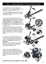
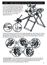
Innova ITM5900 Owner'S Manual Download Page 8

37

19

21

20

4

3

Step 4 

– Height Adjustment Tube and Ankle Holders

8

TIGHTEN ALL NUTS AND BOLTS AT THIS TIME.

1. Install the Footrest (4) into the Height 
Adjustment Tube (3) using 2 Bolts (20), 2 Flat 
Washers (19), and 2 Lock Nuts (21). 

2. Insert the Rear Ankle Holding Tube (10) 
into the Height Adjustment Tube (3) with both 

slots facing UP

. Insert the Bolt (40) with the 

Metal Bushing (39) into the 

bigger hole at 

the bottom 

of the Height Adjustment Tube (3) 

and tighten them with a Flat Washer (19) and 
a Lock Nut (21). 
Insert the U-Shape Holder-Rear (52) with 
Metal Cover (53) to both sides of the Rear 
Ankle Holding Tube (10). Make sure the Metal 
Cover (53) wedges into the slot provided on 
Rear Ankle Holding Tube (10). See detailed 
picture.

4. Insert the 4 Nylon Snaps (69) into the 
holes on Front Ankle Holding Tube (5). You 
must push the Nylon Snaps (69) all the way 
into the Tube so that it blocks the U-Shape 
Holder from sliding out (see detailed 
picture).

For easier installation, pull up on the T Knob 
(37) and push the bar away from the Height 
Adjustment Tube (3).  

3. Insert the Front Ankle Holding Tube (5) 
into the hole on Plastic Cover (43L/R) and 
secure it with Bolt (42) and Flat Washer (19). 
Make sure the 

holes 

on the Tube (5) is 

facing UP.

Slide the U-Shape Holder-Front (64) with 
Plastic Cover (65) into both sides of the 
Front Ankle Holding Tube (5). 

5

69

69

69

Nylon

Snap

Nylon

Snap

21

19

39

40

10

10

19

21

52 53

39

40

53

52

5

64

65

64

65

42

19

43L/R

Slot

Metal Cover

Slots face up

Holes face up

Summary of Contents for ITM5900

Page 1: ...de the Protective Cover for the Angle Selector Pin TO PREVENT unauthorized usage it is strongly recommended you purchase a lock to fasten the Height Adjustment Tube to the Cross Bar KEEP FINGERS feet...

Page 2: ...artment at 408 541 1866 for assistance in the repair or replacement of the product or any covered part Innova Products Inc will repair or replace at its own option the product or any covered part This...

Page 3: ...6 meters on the left and right sides and at least 3 feet 0 92 meters on the front and back sides This area must also include adequate space for emergency dismount See image at the right The inversion...

Page 4: ...omponents STEP 4 Components STEP 2 Components STEP 5 Components Protruding Metal Piece M8x55 M8x50 STEP2 STEP3 STEP1 M8x20 STEP3 STEP4 Hex Wrenches 5 1PC Wrench 13 17 2PCS 1 2 3 4 5 6 7 8 9 10 20 1 2...

Page 5: ...ttached Make sure the Stopper 34 on the Cross Bar 12 is facing out and attach the Cross Bar 12 to the Front Base Frame 9R 9L using 4 Bolts 20 and 2 Metal Support Plates 54 4 Flat Washers 19 and 4 Lock...

Page 6: ...outside of the frame DO NOT tighten Bolts 20 until Bolt 22 is installed Use Bolt 22 and Flat Washer 19 to secure the Right Handlebar 6 to the Rear Base Frame 8R Tighten Bolt 22 and Bolt 20 at this tim...

Page 7: ...Installed Backrest Attach the Pre Installed Backrest 2 47 48 to the Connecting Brackets 11R 11L using 4 Bolts 29 4 Flat Washers 19 and 4 Lock Nuts 21 Screw the Angle Selector Pin 14 into the Incline...

Page 8: ...wedges into the slot provided on Rear Ankle Holding Tube 10 See detailed picture 4 Insert the 4 Nylon Snaps 69 into the holes on Front Ankle Holding Tube 5 You must push the Nylon Snaps 69 all the wa...

Page 9: ...the Protective Cover 59 onto the Right Handlebar 6 with 2 Screws 41 Attach and snap the Front Shield for Cover 71 onto the Protective Cover 59 and secure it onto the Right Handlebar 6 with 2 Screws 4...

Page 10: ...gh the gap under the Headrest 48 and the bottom strap should go through hole at the lower portion of the Backrest 47 Secure the Heat Massage Pad 13 into place by buckling the straps together at the ba...

Page 11: ...terioration such as blistering or cracking CLOSE supervision is necessary when used by or near children invalids or disabled persons DO NOT use on infants or a sleeping or unconscious person NEVER use...

Page 12: ...button to start the heat function The HEAT indicator light is red Press HEAT again to stop the heat function and the indicator light will turn off Press the MANUAL button to cancel the auto mode and s...

Page 13: ...ul interference in a residential installation This equipment generates uses and can radiate radio frequency energy and if not installed and used in accordance with the instructions may cause harmful i...

Page 14: ...ob 38 locks securely into a hole on the Height Adjustment Tube 3 NOTE Before starting make sure the inversion table is at the correct setting to match your height and weight distribution Since each in...

Page 15: ...pand the Adjustable Ankle Holding Tube by pulling up on the T Knob and pushing the Adjustable Ankle Holding Tube outward Step 2 Slide your feet between the U Shape Holders NOTE The back of your ankles...

Page 16: ...ition Try to rely on your center of gravity to return upright DO NOT lift your head try to sit up or just rely on the handlebars to return upright CAUTION By slowly moving your arms back to the starti...

Page 17: ...lied to your feet ankles while inverting Based on reviews and customer feedback many users suggest that using the Inversion Setting of 30 or 45 provides sufficient results 5 How long should I invert A...

Page 18: ...15 Long Pole 1 54 Metal Support Plate 100x38x2 5mm 2 16 Spring 1 55 Screw M4x16mm 3 17 Spacer Base Frame 4 56 Hand Controller 1 18 Round End Cap Base Frame 2 57 Power Adaptor 1 19 Flat Washer 16x 8 5...

Page 19: ...51 51 23 46 46 32 32 1 32 32 54 20 19 19 21 19 19 21 12 34 54 20 1 8R 9L 50 49 35 55 38 41 60 73 48 58 57 Power Adaptor Input Jack 13 56 04 03 72 5 10 15 16 19 19 21 21 20 30 30 33 33 36 36 36 36 37 3...

Page 20: ...ll to prevent tipping There are other storage options for this inversion table Be sure the inversion table is stored safely and make sure it does not slam fall or tip over Contact us for other storage...

Reviews: