Innova ITM5900 Owner'S Manual Download Page 3

3 ft

2 ft

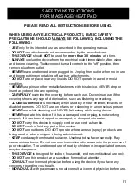
WARNINGS AND PRECAUTIONS

To reduce the risk of serious injury:

·

All users should read and understand all important precautions, instructions, and warnings 

in this manual before using the inversion table. It is your responsibility to familiarize yourself 
with the proper use of the inversion table and the inherent risks of the inversion table (ex. 
falling on your head/neck, pinching, equipment failure, etc.). 

·

It is the responsibility of the owner to ensure that all users of the device are fully informed 

about the proper use of the equipment and all warnings and safety precautions.

·

Users can also read the condensed version of the Warnings and User’s Guidelines on the 

back of the Backrest.

·

Innova Products Inc. assumes no responsibility for personal injury or property damage 

sustained by or through the 

improper use 

of the Inversion Table. 

3

Item Dimensions: 

46.5 in (L) x 28 in (W) x 60-61.60 in (H) 

118 cm x 71 cm x 152.4-156.5 cm

Item Weight: 

59.5 lbs (27 kg)

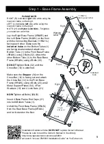
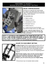
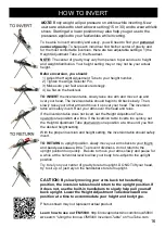
BEFORE USING THE INVERSION TABLE: 

·

The empty space surrounding the inversion table should 

be at least 2 feet (0.6 meters) on the left and right sides 
and at least 3 feet (0.92 meters) on the front and back 
sides. This area must also include adequate space for 
emergency dismount. See image at the right.

· 

The inversion table must be free standing on a stable 

and leveled surface.

· 

Make sure the Safety Pin (Part # 26) is locked into place.

· 

Make sure the Protective Cover is secured on the right 

handlebar.

· 

Be sure to secure your ankles to the ankle holders so 

that your feet are locked snugly into place before 
inverting.

· 

The safety level of the inversion table can be 

maintained only if it is examined regularly for 
damage and wear and tear from regular usage. 

· 

Please replace all missing or defective 

components or worn out parts immediately 
and/or keep the inversion table out of use 
until item has been replaced or repaired.

· 

Parts most susceptible to wear and tear:

1) U-Shape Holder (Part #52)
2) U-Shape Holder (Part #64)

.

2 ft

3 ft

Pinch Warning on 

the Side Cover

Angle Selector 
Pin Warning

Ankle Lock and  
Other Warnings 

User's Warning & 

Weight Capacity

Height 
Adjustment 
Knob Label

User's Guidelines 
& Warning 
on the back of 
Backrest

WARNING LABELS

Call us to replace warning labels                                        

if damaged, illegible or removed.

Headrest 
Adjustment 
Label

Pinch Warning

WARNING: Maximum Weight Capacity is 300 LBS

Summary of Contents for ITM5900

Page 1: ...de the Protective Cover for the Angle Selector Pin TO PREVENT unauthorized usage it is strongly recommended you purchase a lock to fasten the Height Adjustment Tube to the Cross Bar KEEP FINGERS feet...

Page 2: ...artment at 408 541 1866 for assistance in the repair or replacement of the product or any covered part Innova Products Inc will repair or replace at its own option the product or any covered part This...

Page 3: ...6 meters on the left and right sides and at least 3 feet 0 92 meters on the front and back sides This area must also include adequate space for emergency dismount See image at the right The inversion...

Page 4: ...omponents STEP 4 Components STEP 2 Components STEP 5 Components Protruding Metal Piece M8x55 M8x50 STEP2 STEP3 STEP1 M8x20 STEP3 STEP4 Hex Wrenches 5 1PC Wrench 13 17 2PCS 1 2 3 4 5 6 7 8 9 10 20 1 2...

Page 5: ...ttached Make sure the Stopper 34 on the Cross Bar 12 is facing out and attach the Cross Bar 12 to the Front Base Frame 9R 9L using 4 Bolts 20 and 2 Metal Support Plates 54 4 Flat Washers 19 and 4 Lock...

Page 6: ...outside of the frame DO NOT tighten Bolts 20 until Bolt 22 is installed Use Bolt 22 and Flat Washer 19 to secure the Right Handlebar 6 to the Rear Base Frame 8R Tighten Bolt 22 and Bolt 20 at this tim...

Page 7: ...Installed Backrest Attach the Pre Installed Backrest 2 47 48 to the Connecting Brackets 11R 11L using 4 Bolts 29 4 Flat Washers 19 and 4 Lock Nuts 21 Screw the Angle Selector Pin 14 into the Incline...

Page 8: ...wedges into the slot provided on Rear Ankle Holding Tube 10 See detailed picture 4 Insert the 4 Nylon Snaps 69 into the holes on Front Ankle Holding Tube 5 You must push the Nylon Snaps 69 all the wa...

Page 9: ...the Protective Cover 59 onto the Right Handlebar 6 with 2 Screws 41 Attach and snap the Front Shield for Cover 71 onto the Protective Cover 59 and secure it onto the Right Handlebar 6 with 2 Screws 4...

Page 10: ...gh the gap under the Headrest 48 and the bottom strap should go through hole at the lower portion of the Backrest 47 Secure the Heat Massage Pad 13 into place by buckling the straps together at the ba...

Page 11: ...terioration such as blistering or cracking CLOSE supervision is necessary when used by or near children invalids or disabled persons DO NOT use on infants or a sleeping or unconscious person NEVER use...

Page 12: ...button to start the heat function The HEAT indicator light is red Press HEAT again to stop the heat function and the indicator light will turn off Press the MANUAL button to cancel the auto mode and s...

Page 13: ...ul interference in a residential installation This equipment generates uses and can radiate radio frequency energy and if not installed and used in accordance with the instructions may cause harmful i...

Page 14: ...ob 38 locks securely into a hole on the Height Adjustment Tube 3 NOTE Before starting make sure the inversion table is at the correct setting to match your height and weight distribution Since each in...

Page 15: ...pand the Adjustable Ankle Holding Tube by pulling up on the T Knob and pushing the Adjustable Ankle Holding Tube outward Step 2 Slide your feet between the U Shape Holders NOTE The back of your ankles...

Page 16: ...ition Try to rely on your center of gravity to return upright DO NOT lift your head try to sit up or just rely on the handlebars to return upright CAUTION By slowly moving your arms back to the starti...

Page 17: ...lied to your feet ankles while inverting Based on reviews and customer feedback many users suggest that using the Inversion Setting of 30 or 45 provides sufficient results 5 How long should I invert A...

Page 18: ...15 Long Pole 1 54 Metal Support Plate 100x38x2 5mm 2 16 Spring 1 55 Screw M4x16mm 3 17 Spacer Base Frame 4 56 Hand Controller 1 18 Round End Cap Base Frame 2 57 Power Adaptor 1 19 Flat Washer 16x 8 5...

Page 19: ...51 51 23 46 46 32 32 1 32 32 54 20 19 19 21 19 19 21 12 34 54 20 1 8R 9L 50 49 35 55 38 41 60 73 48 58 57 Power Adaptor Input Jack 13 56 04 03 72 5 10 15 16 19 19 21 21 20 30 30 33 33 36 36 36 36 37 3...

Page 20: ...ll to prevent tipping There are other storage options for this inversion table Be sure the inversion table is stored safely and make sure it does not slam fall or tip over Contact us for other storage...

Reviews: